background image

BAS-SVX40B-EN

7

General Information

Specifications and Agency Compliance
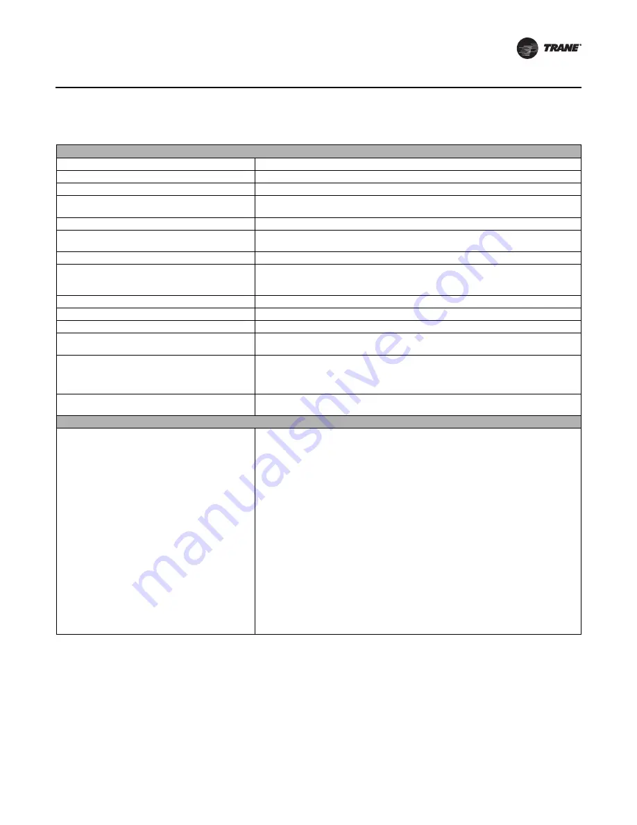
Specifications

Operating temperature

-40 to 158ºF (-40 to 70ºC)

Storage temperature

-40 to 185ºF (-40 to 85°C)

Storage and operating humidity range

5% to 95% relative humidity (RH), non-condensing

Voltage

24 Vac/Vdc nominal ± 10%
If using 24 Vac, polarity must be maintained.

Receiver power consumption

<2.5 VA

Housing material

Polycarbonate/ABS (suitable for plenum mounting), UV protected,  
UL 94: 5 VA flammability rating

Mounting

3.2 in (83 mm) with 2 supplied mounting screws

Range

(a)

Open range: 2,500 ft (762 m) with packet error rate of 2%
Indoor: Typical range is 200 ft (61 mm); actual range is dependent on the environment. 
See BAS-SVX55 for more detail.

Output power

North America: 100 mW

Radio frequency

2.4 GHz (IEEE Std 802.15.4-2003 compliant) (2405–2480 MHz, 5 MHz spacing)

Radio channels

16

Address range

Group 0–8
Network 1–9

Mounting

Fits a standard 2 in. by 4 in. junction box (vertical mount only). Mounting holes are spaced 
3.2 in. (83 mm) apart on vertical center line. Includes mounting screws for junction box 
or wall anchors for sheet-rock walls. Overall dimensions: 2.9 in. (74 mm) by 4.7 in. 
(119

 mm)

Wireless protocol

ZigBee PRO—ZigBee Building Automation Profile, ANSI/ASHRAE Standard 135-2008 
Addendum q (BACnet™/ZigBee)

Agency compliance

United States

UL listed: UL 94, 5 VA flammability rating and UL916.
Energy Management Equipment FCC CFR47, Sec. 15.247 & subpart E, Digital Modulation 
Transmission with no SAR (FCC ID: TPF-251701).
This device complies with part 15 of the FCC Rules. Operation is subject to the following 
two conditions: (1) This device may not cause harmful interference, and (2) this device 
must accept any interference received, including interference that may cause undesired 
operation. 
Changes or modifications not expressly approved by the manufacturer for compliance 
could void the user’s authority to operate the equipment.

Note:

This equipment has been tested and found to comply with the limits for a Class B digital 

device, pursuant to part 15 of the FCC Rules. These limits are designed to provide 

reasonable protection against harmful interference in a residential installation. This 

equipment generates, uses and can radiate radio frequency energy and, if not installed 

and used in accordance with the instructions, may cause harmful interference to radio 

communications. However, there is no guarantee that interference will not occur in a 

particular installation. If this equipment does cause harmful interference to radio or 

television reception, which can be determined by turning the equipment off and on, the 

user is encouraged to try to correct the interference by one or more of the following 

measures: 

• Reorient or relocate the receiving antenna. 

• Increase the separation between the equipment and receiver. 

• Connect the equipment into an outlet on a circuit different from that to which the 

receiver is connected. 

• Consult the dealer or an experienced radio/TV technician for help. 

Summary of Contents for MOD02422

Page 1: ...knowledge and training Improperly installed adjusted or altered equipment by an unqualified person could result in death or serious injury When working on the equipment observe all precautions in the...

Page 2: ...at any time and to make changes to its content without obligation to notify any person of such revision or change Trademarks All trademarks referenced in this document are the trademarks of their resp...

Page 3: ...WCI 13 Controller Applications 13 Repeater Applications 17 Establishing the Network 18 WCI LEDs and Buttons 18 Three Ways to Establish a Wireless Network 20 Establishing the Network After Tracer SC I...

Page 4: ...ppendix Using the Tracer TU Service Tool with Wireless Networks 28 Requirements for Joining 28 Joining Tracer TU with a Wireless Network 28 Managing a Wireless Network and Devices 30 Connecting to a D...

Page 5: ...s that can be installed at a site is determined by the applicable Tracer SC license which specifies the total number of controllers For information about installing aWCI on aTracer SC see Mounting and...

Page 6: ...rness and mounting hardware intended for indoor installations X13790902010 NO BAY SEN01807 For flush mount applications Wiring harness not included X13790941010 BAYWCII200A MOD02422 Outdoor model incl...

Page 7: ...Equipment FCC CFR47 Sec 15 247 subpart E Digital Modulation Transmission with no SAR FCC ID TPF 251701 This device complies with part 15 of the FCC Rules Operation is subject to the following two cond...

Page 8: ...lectriques ou de t l vision ceci pouvant tre d termin en allumant et en teignant l quipement l utilisateur est encourag essayer de corriger l interf rence en utilisant un ou plusieurs des moyens suiva...

Page 9: ...eater to bridge the signal between a WCI that is out of the radio range of the other WCIs see Repeater Applications p 17 When choosing a location for a repeater WCI consider the availability of a 24 V...

Page 10: ...10 BAS SVX40B EN Location Considerations Consequently the design range between these devices is shorter Based on our tests we recommend a design range of 100 feet...

Page 11: ...rs to all of the networks that communicate with the sameTracer SC 2 Set the right NET rotary address switch for eachWCI that is to be on the same network to an identical number If there are multiple n...

Page 12: ...sses so that no two wireless zone sensors sharing the same address are within radio range of each other Addresses above 127 may be used for Wireless Comm systems See the Wireless Comm Network Design B...

Page 13: ...er 3 Secure the backplate to the mounting surface using appropriate hardware M3 5 x 20 mm self drilling screws are provided 4 Attach the 4 connector screw terminal block on the wiring harness to the r...

Page 14: ...I remotely then you only need to run one piece ofTrane purple wire 2 conductors 1 shield for the comm link Trane recommends that you ground the shield at the UC the BCI or the PM014 Note To wire the W...

Page 15: ...Gray LINK Blue LINK Black Ground Red 24 Vdc Connect both 2 connector screw terminal blocks to either of the IMC terminals on the PM014 WCI WCI WCI WCI WCI WCI WCI WCI Tracer SC PM014 Notes A maximum o...

Page 16: ...LINK Blue LINK Black Ground Red 24 Vdc VAC 24 BI1 BI2 BI3 LINK IMC 24 VDC IMC Jumper LINK LINK 24 Vdc WCI BCI I Attach jumper at BI1 to enable wireless communication Gray LINK Blue LINK Black Ground R...

Page 17: ...wiring harness 6 Connect the red 24Vdc Vac wire and black ground wire through the opening in the backplate Figure 5a or the bottom exit port Figure 5b to a 24 V power source AC or DC Figure 11 Wiring...

Page 18: ...cer SC designates a WCI as the network coordinator and opens the network for joining Removes a member WCI from the network see Removing a WCI from a Network p 24 Disbands the network see Disbanding a...

Page 19: ...ith the WCI Coordinator LED yellow CRD On solid WCI is network coordinator Open Net LED yellow OPEN NET On solid Network is open for joining Off Network is closed Reception LED yellow RX LINK Flickers...

Page 20: ...seTracerTU to open the network 3 Observe the green NWK LED illuminate On the coordinator WCI indicating that it has joined its own network On each additional WCI as it joins the network Note Typically...

Page 21: ...conds The network will disband 2 Install an addressed WCI on theTracer SC following addressing and wiring instructions see WCI Addressing p 11 and Mounting and Wiring the WCI p 13 After power is resto...

Page 22: ...n see Setting Wireless Zone Sensor Receiver Addressing p 12 Figure 13 Wireless zone sensor receiver association Notes To observe the radio signal strength between the sensor and receiver press theTest...

Page 23: ...tton on a member WCI will open only that one WCI 2 Observe the green NWK LED illuminate on a WCI that joins the network Adding Coordinators to aTracer SC ATracer SC can have a total of eightWCIs insta...

Page 24: ...ol of the unit controller Replacing a WCI on a Network See Replacing a Failed WCI p 26 Closing the Network To preventWCIs from joining an open network indicated by an illuminated OPEN_NET LED you can...

Page 25: ...er to the WCI Ensure that the WCI is wired properly to the Tracer SC Wireless link on the Tracer SC Ensure that the wireless link on the Tracer SC is enabled and configured to match WCI address and is...

Page 26: ...dinator WCI will re initiate the network as soon as power is returned Signal obstruction If an obstruction causes communication to be lost the coordinator WCI will re initiate the network as soon as c...

Page 27: ...er SC The network will re form itself New coordinator WCI when noTracer SC is present 1 Set or verify if pre addressed the rotary address switches on the new WCI 2 Attach the terminal block on the wir...

Page 28: ...nts for joiningTracerTU to a wireless network are TracerTU version 8 2 minimum TheTracerTU Communications Adapter Wireless connected to the service tool laptop Note For instructions onTracerTU Communi...

Page 29: ...required An open padlock icon indicates that noTracer SC login is required Figure 15 Wireless Network Utilities 4 Select the network you wantTracerTU to join Click the Join button Note TracerTU can j...

Page 30: ...manage the network and the devices on it by connecting to a device on the network Connecting to a Device To connect to a device 1 From the Wireless Network Utilities screen select the Network Devices...

Page 31: ...ment To access the menu select Wireless from theTools menu Figure 19 Wireless menu TheseTools menu options perform the following functions Network Health Displays theWireless Network Summary Report sh...

Page 32: ...onse to a comm request from each device You can also access the Wireless Network Summary Report by clicking Report on the Network Devices tab Figure 20 Wireless Network Summary Report Click Load Map t...

Page 33: ...Network Details tab see Figure 22 p 33 Figure 22 Network Details tab Sensor Health Status Provides an alternate way to view the Wireless Sensor Status tab see Figure 23 Figure 23 Wireless Sensor Stat...

Page 34: ...st be attached to the network coordinator Join Network Select to join the network Appears when you are connecting to a member WCI It is grayed out if you have already joined the network Create Network...

Page 35: ...troller but a wireless sensor is in the area the wireless sensor has priority and the unit controller may start using the wireless sensor even though a sensor is wired to it In such a case you must di...

Page 36: ...controls and HVAC systems comprehensive building services and parts For more information visit www Trane com Trane has a policy of continuous product and product data improvement and reserves the rig...

Reviews: