background image

47

PKG-SVX19B-E4

NOTE: After having removed the side panels, the non-

removable protective panel, blocks accessibility to the inside 

of the machine.

Removal of the rear panels

To  remove  the  rear  panels,  carry  out  the  following 

procedure:

•  unscrew, using a star screwdriver, the screws which fix 

the panel;

•  firmly hold the panel and pull.

Internal protection panels

The technical compartment, the electric heaters and the 

autotransformer fans are protected by internal protection 

panels for safety reasons and to allow the opening of the 

external panels without triggering the unit’s safety alarms. 

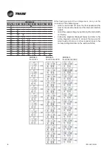
In the figures below the different types of internal protection 

panels are shown on various types of machines.

Before removing the internal protection panels, 

disconnect the power supply by turning the main isolating 

switch  D5 to position “O”, then wait until the fans stop and 

the electrical heaters cool down.

MODELS EUCB - EUCV 0070, 0100, 0120, 0170,0200, 

0250

MODELS EDCB - EDCV 0070, 0100, 0120, 0170,0200, 

0250, 0270

MODELS EDCB 0340, 0400, EDCV0340, 0400

Summary of Contents for EDAB 1106A

Page 1: ...nit Direct Expansion Unit EDAB EUAB EDAV EUAV EDWB EUWB EDWV EUWV 1105 1106 2107 2207 2109 2209 2111 2211 2113 2213 2216 2218 2222 4222 2225 4225 4228 Chilled Water Unit EDCB EUCB EDCV EUCV 0070 0100 0120 0170 0200 0250 0270 0340 0400 Technical guide ...

Page 2: ...PKG SVX19B E4 2 ...

Page 3: ...n chilled water cooled models only 34 Setting the air flow sensor 34 Setting the dirty filter sensors 35 MAINTENANCE 35 Check every three months 35 Check every six months 35 Annual checks 35 Checks to be performed every sixty months 35 Cleaning and replacing the filters 36 Troubleshooting 37 MERCURY CHILLED WATER 41 Technical characteristics 41 Operating description 42 Name and description of the ...

Page 4: ...e instructions are followed by a list of the possible typical CER 2002 codes to allow an easier disposal of the machine parts WARNING Observe the safety precautions at work wearing the suitable individual protection devices IPD and using the appropriate equipments WARNING Maintenance and service operations disassembling included must be performed by qualified and expert personnel aware of the esse...

Page 5: ...ith an alloy containing a large amount of silver FANS Remove the fans Disassemble the metal frame and proceed with the recycling of the metal alloy Materials electro mechanical elements iron wrecks WARNING The fans of some machine models are integral part of the carrying structure Removing the fans can compromise the stability of the frame We recommend to pay attention during disassembling operati...

Page 6: ... forklift truck or any other lifting equipment or means of transport Adopt all of the cautions provided by the relevant safety standards in order to prevent any possible damage to people or objects Warnings for installation Any type of work on the electrical installation must only be carried out by specialised technicians who are experts in this field Specialised technical personnel must use appro...

Page 7: ... precision air conditioners are designed for environments which are characterised by the presence of highly technologically advanced equipment telecomms and internet centres data processing rooms and any type of environment which is characterized by high concentrations of power The Mercury series consists of 2 types of conditioners Direct expansion Chilled water DOWNFLOW Downflow units with downwa...

Page 8: ...r absorbed by the unit and the single components Current absorbed by the unit and the single components The set points of the cooling circuit pressostatic valve and safety valve Type of refrigerant Loading or pre loading of each cooling circuit Indicative cooling capacity Number of compressors installed Number of cooling circuits Power supply voltage A 400 V 3Ph N 50 Hz rev D EDAB2113A H SERIAL No...

Page 9: ...RAVITY shows the centre of gravity of the packaged unit KEEP AWAY FROM HEAT the unit must be stored away from heat sources THIS SIDE UP indicates the correct position of the packaged unit TEMPERATURE LIMITS the packaged unit must be stored in a place within the indicated temperature limits DO NOT USE HOOKS do not lift the packaged units using hooks DO NOT STACK the packaged units must not be stack...

Page 10: ... voltage V 400V 3ph N 50Hz Model EDAB EUAB 2111A 2211A 2113A 2213A 2216A 2218A Height mm 1960 1960 1960 1960 1960 1960 Width mm 1721 1721 1721 1721 2172 2172 Depth mm 865 865 865 865 865 865 Weight kg 548 559 575 585 714 714 Number of refrigerant circuits 1 2 1 2 2 2 Number of compressors 2 2 2 2 2 2 Power supply voltage V 400V 3ph N 50Hz Model EDAB 2222A 4222A 2225A 4225A 4228A Height mm 2175 217...

Page 11: ...NS Model EDAV EUAV 2111A 2211A 2113A 2213A 2216A 2218A Height mm 1960 1960 1960 1960 1960 1960 Width mm 1720 1720 1720 1720 2171 2171 Depth mm 865 865 865 865 865 865 Weight kg 548 559 575 585 714 714 Number of refrigerant circuits 1 2 1 2 2 2 Number of compressors 2 2 2 2 2 2 Power supply voltage V 400V 3ph N 50Hz Model EDAV 2222A 4222A 2225A 4225A 4228A Height mm 2175 2175 2175 2175 2175 Width m...

Page 12: ... 1120 Number of refrigerant circuits 2 2 2 Number of compressors 4 4 4 Power supply volatge V 400V 3 ph N 50 Hz CHILLED WATER DIRECT EXPANSION UNITS WITH BACKWARD CURVED BLADE FANS Model EDWB EUWB 1106A 2109A 2113A 2216A 2218A Height mm 1960 1960 1960 1960 1960 Width mm 1010 1310 1720 2171 2171 Depth mm 750 865 865 865 865 Weight kg 310 430 575 714 714 Number of refrigerant circuits 1 1 1 2 2 Numb...

Page 13: ...ation extremely simple eliminating the need for any site installed refrigerant pipework Operating description AIR COOLED DIRECT EXPANSION UNITS DXA The air cooled DX units extract heat from the room and transfer it to the outside using air cooled refrigerant heat exchangers condensers The room unit and external condenser form an autonomous sealed circuit once installed The TRANE remote condensers ...

Page 14: ...description of the main components A User terminal B Electrical panel door C Cover panels D Electrical panel E Filters F Fans G Cooling circuit H Brazedplateheatexchanger present in chilled water models MODELS ED EU 1105 2218 MODELS ED EU 2222 4228 B ...

Page 15: ... machine C Cover panels Allow access to the internal components of the machine D Electrical panel D1 Magnetothermic auxiliary heater optional humidifier optional fans compressors D2 Interface board D3 Dirty filter sensor D4 Air flow sensor D5 Main switch D6 Terminal board D7A Input output electrical supply cables D7B Input output electrical auxiliary cables D7C Input output condensing unit supply ...

Page 16: ... Circuit Exit G7 Circuit entrance G8 Liquid receiver G9 Dehydration filter G10 Flow sight glass G11 Electronic thermostatic valve G12 Evaporating coil H Brazed plate heat exchanger present on water cooled units H1 Input output hydraulic circuit I Room temperature and humidity sensor H H1 G1 G3 G4 G5 G6 G7 G8 G10 G11 G9 G12 I G2 ...

Page 17: ...allation on raised access flooring using mounting frames or appropriate floor stands supplied on request from Trane However the upflow units upwards air flow with air intake through the rear or front can also be installed on floors which are not raised The area of installation must have the following characteristics to facilitate maintenance leave a clearance distance D of at least 700mm free in f...

Page 18: ...e floor stand carry out the following procedures position the unit on the floor stand fix the unit to the floor stand using the M8 screw inserts found on the base of the unit Door opening and removal of the panels Door opening To open the door of the unit carry out the following procedure push the button and pull the handle lightly outwards turn the handle downwards until the door opens Removal of...

Page 19: ...rnal panels without triggering the unit s safety alarms In the figures below the different types of internal protection panels are shown on various types of machines Before removing the internal protection panels disconnect the power supply by turning the main isolating switch D5 to position O then wait until the fans stop and the electrical heaters cool down MODELS ED 1105 2218 MODELS EU 1105 221...

Page 20: ...re that it is not possible to reconnect the power during the operation WARNING The power supply voltage must be 10 To carry out the electrical connections of the machine to the power supply carry out the following procedures use suitable equipment to check the efficiency of the grounding system checkthatthevoltageandnetworkfrequencycorrespond to those of the machine see identification label open t...

Page 21: ... tray of the humidifier until both siphons are full Connection to the gas drain The cooling circuit is equipped with a safety valve for the discharge of the refrigerant gas The intervention of the valve pressurises the discharge of the refrigerant fluid possibly also to high temperatures in the case of installation in a closed environment where there is the risk of causing damage to people nearby ...

Page 22: ...ating levels The minimum diameters needed to guarantee the flow of oil can be found in Graphics 1 2 for the horizontal and vertical lines respectively In the installation of machines which have more compressors per circuit the vertical discharge line sized in order to guarantee the flow of oil at minimum load may cause excessive loss of load when operating at its maximum level in this case it is p...

Page 23: ...24mm R410A Graphic 1 Discharge tube horizontal line DP L kPa m 0 0 2 0 4 0 6 0 8 0 10 0 12 0 14 0 16 0 18 0 0 10 20 30 40 50 12mm 14mm 16mm 18mm 20mm 22mm 24mm 28mm Cooling capacy circuit kW DP L kPa m DP L kPa m Cooling capacy circuit kW DP L pressure drop per meter based on R410A Discharge tube vertical line Graphic 2 ...

Page 24: ...VX19B E4 24 Graphic 3 5 0 5 10 15 20 25 30 35 40 Equivalentline m 3 2 1 14 12 10 8 7 6 5 4 3 2 1 Equivalent lilne m Unacceptable Acceptable Recommended DP L DP L DP L DP L DP L DP L DP L DP L DP L DP L DP L ...

Page 25: ...Kpa m 14mm DP L 3 0 Kpa m 2 Graphic 3 Operating at 100 2 compressors Pipe size 16mm DP L 4 1 Kpa m Acceptable Pipe size 14mm DP L 8 8 Kpa m Acceptable Raccomanded sizes are both 14 mm or 16 mm Cooling capacity circuit at partial load operation 50 Cooling capacity circuit at full load operation 100 E quivalent length No Chart 3 Pipe s izing Type of line Chart 2 Vertical line Chart1 Horizontal line ...

Page 26: ...id migration during start up Liquid line external diameters Remote air cooled condenser EDA EUA MODEL 1105 1106 2107 2207 2109 2209 Number Suggested model 1 2 1 x CAP0661 1 x CAP0661 1 x CAP0801 2 x CAP0331 1 x CAP1011 2 x CAP0361 EDA EUA MODEL 2111 2211 1113 2213 2216 2218 Number Suggested model 1 2 1 x CAP1301 2 x CAP0511 1 x CAP1301 1 x CAP1802 2 x CAP0661 1 x CAP2002 2 x CAP0801 1 x CAP3002 2 ...

Page 27: ...igerant line itself preferably less than 30 m therefore the diameter of the welding connections prepared by Trane may not match with the diameter of the pipes if so we recommend to use the special reductions Dry coolers EDW EUW MODEL 1106 2109 2113 2216 2218 Number Suggested model 1 x RAL1500 1 x RAL1500 1 x RAL2300 1 x RAL3600 1 x RAL3600 Max outdoor temperature 40 0 C 40 0 C 43 5 C 44 2 C 43 4 C...

Page 28: ...r an extremely extensive system it will be necessary to break the vacuum with anhydrous nitrogen and then repeat the evacuation procedure as described break the vacuum by performing a preload in liquid phase from the R410A coolant cylinder after having started the compressor slowly complete the loading phase until the pressure within the lines has been stabilised and the gaseous bubbles have disap...

Page 29: ...ase the pressure of the supply must not be less then 200 kPa 2 bar WARNING Do not use chilled water with an evaporating tower because the condensers will quickly become encrusted with limescale The condenser must be connected to the chilled water distribution network paying attention to the direction of the water inlet and outlet The condensers are supplied by water pumped in a closed circuit and ...

Page 30: ...the refrigerant may occur in the casing of the compressor which may cause foaming of the oil and consequent damage by the lack of lubrification It is recommended that the main switch is not turned off during weekly breaks wait at least 12 hours before start up so that the oil in the compressors warms up sufficiently open the shut off valves I5 of the refrigerating circuits check that the remote co...

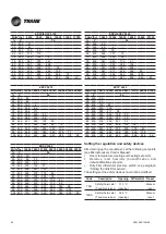
Page 31: ... 200V 210V 220V 230V Models 0721 1822 230V 250V 260V 270V 280V 290V 300V 310V 320V 340V 360V 380V 400V Models 2222 2242 2522 2542 2842 3342 150V 180V 200V 230V 240V 260V 280V 300V 320V 340V 360V 380V 400V In the following table the maximum pressure available expressed in Pa for each voltage level of the transformer is indicated The values are given for the maximum air flow expressed in m3 h F1 E A...

Page 32: ...voltage by positioning the main switch to 0 D5 Follow the diagrams displayed below and refer to the wiring diagram enclosed to connect the two electric wires found on the fan or on the connector block to the corresponding terminals on the autotransformer MODELS da 2107 2218 MODELS da 2222 4228 MODELS 1105 1106 ATR1 ATR2 ATR1 ATR2 ATR1 ATR2 ATR1 ATR2 ATR1 ATR2 ATR1 ATR2 ATR1 ATR2 ATR1 ATR2 ATR1 ATR...

Page 33: ...mum air flow expressed in m3 h E AV E WV Air and water condensing direct expansion unit 20 Pa Refrigerant R410A 20 Pa EU4 EU5 Post heating Post heating EU5 Power supply voltage 0511A 0611A 58 59 59 60 0721A 0722A 0921A 0922A 1021A 1022A 68 69 69 70 1121A 1122A 1321A 1322A 61 63 62 64 1422A 1622A 1822A 70 71 71 72 2222A 2242A 62 63 63 64 2522A 2542A 65 66 66 67 2842A 66 67 67 69 Model E AV E WV 110...

Page 34: ...the air flow it may be necessary to calibrate the instruments after installation checking that the contact closes when the fans are in operation To set the FS pressure switch carry out the following procedure simulate a fan fault by stopping a fan check that the pressure switch intervenes if the pressure switch does not intervene gradually increase the setting until the pressure switch switches of...

Page 35: ... the evaporating fan s check the fittings operation and absorption of the compressor s check and if necessary replace the seal of the refrigerant circuit s and tighten the joints and connections of the unit check and top up if necessary the refrigerant gas and or oil check and if necessary reset the regulation devices setting check and if necessary replace the seal of the hydraulic circuits s and ...

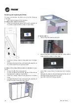
Page 36: ...hecking the direction of the air flow which was previously noted reposition the filter blocking supports Cleaning and replacing the filters Models ED 2222 4228 To clean and replace the filters carry out the following procedures remove the front cover of the filters by turning counterclockwise the panels screws remember the direction of the air flow indicated on the label of each filter and draw th...

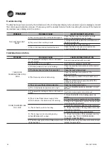
Page 37: ...rcuit of the heaters 3 If there is a heater alarm remove the cause and re set the safety thermostat C The hot water coil is not working 1 Check the hot water capacity and temperature 2 Check the function of the regulation valve see valve and servomotor D The hot gas coil is not working during dehumidification with re heat 1 Check the hot gas 3 way valve function 2 Check the function of the compres...

Page 38: ... control panel and or sensors work properly PROBLEM POSSIBLE CAUSE CHECK CORRECTIVE ACTION ABSENT OR LOW AIR FLOW A There is no power to the fans Check the power supply to the fans B The air filters are clogged dirty filter alarm enabled 1 Shake the dust out of the cartridge and clean with a vacuum cleaner Replace the filter if it is completely blocked 2 Check the correct setting of the dirty filt...

Page 39: ...pressor discharge pressure A The condensing pressure control system is not functioning efficiently 1 Check the fan function of the condenser and of the relative protection re set or replace the faulty fans 2 Check the setting and function of the fan speed regulator of the remote condenser B The system discharge pressure is too high See HIGH COMPRESSOR DISCHARGE PRESSURE LOW COMPRESSOR DISCHARGE PR...

Page 40: ...CTIVE ACTION THE COMPRESSOR S DOESN T DON T WORK A The short circuit protection has intervened Re set the automatic switch and check the cause of the short circuit Before re starting the compressor check the resistance and continuity of the compressor motor windings B The contactor is not working Check the contacts and the contactor coil THE COMPRESSOR S INTERNAL PROTECTION INTERVENES A A phase is...

Page 41: ...070 0100 Height mm 1960 1960 Width mm 1010 1010 Depth mm 750 865 Weight kg 220 306 Chilled water flow kW 18 6 25 5 Chilled water flow l h 3240 4480 Electric supply voltage V 400V 3ph N 50Hz Based on 24 C 50 air temperature ESP 20Pa chilled water 7 12 C ethylene glycol 0 Based on 24 C 50 air temperature ESP 20Pa chilled water 10 15 C ethylene glycol 0 Model EDCB 0270 0340 0400 Height mm 1960 1960 1...

Page 42: ...0 Depth mm 865 865 865 Weight Complete version 1 kg 502 720 740 Chilled water flow l h 16887 19000 21680 Chilled water flow l h 13063 14675 16059 Electric supply voltage V 400V 3ph N 50Hz Model EDCV EUCV 0070 0100 0120 0170 0200 0250 Height mm 1960 1960 1960 1960 1960 1960 Width mm 1010 1310 1310 1721 2172 2172 Depth mm 750 865 865 865 865 865 Weight kg 280 306 314 395 443 458 Chilled water flow l...

Page 43: ...sation and re set of alarms when the alarm is activated it flashes red A3 PRG key access to the configuration menu A4 ESC key exit from the screens A5 UP key scroll through the menu A6 ENTER key confirm A7 DOWN key scroll through the menu B Electrical panel door Allows access to the electrical panel of the machine A User terminal B Electrical panel door C Cover panels D Electrical panel E Filters ...

Page 44: ...of air into the room F1 ATR Transformer allows the setting of the fan rotation speed of the ED B and EU B units D Electric panel D1 Magnetothermic auxiliary heater optional humidifier optional fans D2 Interface board D3 Dirty filter sensor D4 Air flow sensor D5 Main switch D6 Terminal board D7A Input output electrical supply cables D7B Input output electrical auxiliary cables D7C Input output sign...

Page 45: ...ntee conditions Unloading the unit To unload the unit from the pallet carry out the following procedure move the pallet as near as possible to where the unit is to be installed use a ramp to avoid any damage to the unit during unloading remove the blocking screws which fix the unit to the pallet carefully push the unit along the ramp until it reaches the floor Characteristics of the installation a...

Page 46: ...at least 5 mm thick should be fitted between the raised floor panels and the mounting frame which should also be isolated from the metallic floor structure position the unit of the mounting frame and fix it using the M8 screw inserts found on the base of the unit Air conditioning unit Raised floor Flexible seal Flexible seal Mounting frame Installation on flooring which is not raised Installation ...

Page 47: ...otransformer fans are protected by internal protection panels for safety reasons and to allow the opening of the external panels without triggering the unit s safety alarms In the figures below the different types of internal protection panels are shown on various types of machines Before removing the internal protection panels disconnect the power supply by turning the main isolating switch D5 to...

Page 48: ...e to the power supply carry out the following procedures use suitable equipment to check the efficiency of the grounding system checkthatthevoltageandnetworkfrequencycorrespond to those of the machine see identification label open the door of the electrical panel remove the plastic screen of the electrical panel using a star screwdriver POWER SUPPLY CABLE at customers at care POWER SUPPLY CABLE at...

Page 49: ... cable inlet D7B DIGITAL CONFIGURABLE INPUTS Terminal board 51 20 User ON OFF Remote Flooding sensor SAS Terminal board 52 20 User ON OFF Remote Fire smoke SFF Terminal board 50 20 User ON OFF Remote Tools ATA BTA AUA BUA Terminal board 60 20 Summer Winter remote Water flow meter Connection of the humidifier additional fitting and to the storm sewer system WARNING The water discharged from the hum...

Page 50: ...eding valve on the upper part of the cooling coil and wait for the water to come out Hydraulic connections For all hydraulic connections except for the condensate drain it is recommended to use the following flexible hoses to avoid the transmission of vibrations and to allow the unit to be moved three piece joints near the connections shut off valves to isolate the unit from the water circuit if p...

Page 51: ...ont panels press the ENTER key A6 of the user terminal a sliding bar and a ventilator icon will appear on the display if an alarm is indicated consult the user interface manual mP40 check the rotation direction of the fans the correct direction is indicated with an arrow which is on the fan itself If the rotation is in the wrong direction invert two of the three power supply phases following the i...

Page 52: ...tion WARNING In the case of a unit with ducts the load loss from the exhaust duct must be less than 100 Pa In the following table the voltage levels for each model working in the standard version are given Models V 0070 195 0100 0200 310 0120 340 0170 260 0250 320 0270 340 0340 280 0400 300 HOW TO ADJUST FAN SPEED In the E CB three phase models the rotation speed of the fans be varied by using the...

Page 53: ... 17 380 380 256 204 105 88 57 400 418 294 242 142 125 94 20 EDCB EUCB 0340 FA m3 h 15300 19000 23000 24777 26000 28000 28520 V Pa 150 180 55 200 131 3 230 235 103 240 267 134 260 327 191 45 280 381 244 90 20 300 430 291 131 57 5 320 473 333 168 91 36 340 511 370 202 122 66 360 544 402 232 151 94 380 571 429 259 178 120 21 400 592 451 282 201 144 46 20 EDCB EUCB 0120 FA m3 h 5700 7000 8000 9000 102...

Page 54: ... below and refer to the wiring diagram enclosed to connect the two electric wires found on the fan or on the connector block to the corresponding terminals on the autotransformer MODELS from 0100to 0270 MODELS from 0340 to 0400 MODELS from 0070 EDCB 0400 FA m3 h 15940 19000 23000 25200 26500 27500 28100 V Pa 150 180 20 200 96 230 200 89 240 232 120 260 292 177 28 280 346 230 73 300 395 277 114 20 ...

Page 55: ...00 0 55 400 60 60 400 118 80 65 400 181 117 70 400 250 190 75 75 400 335 267 157 59 80 400 420 348 242 153 85 400 508 432 331 250 22 90 400 595 521 422 345 130 95 400 687 614 517 445 240 100 400 784 724 615 525 325 20 EDCV EUCV 0100 FA m3 h 5700 7000 8000 10000 11000 11830 V Pa 50 400 47 55 400 105 60 400 167 47 65 400 233 122 4 70 400 304 201 90 75 400 380 283 178 80 400 459 368 269 85 400 543 45...

Page 56: ... must not be modified EDCV 0340 FA m3 h 16900 18500 21500 24875 26500 28000 32250 V Pa 55 400 20 60 400 82 26 65 400 148 96 70 400 218 169 57 75 400 295 247 140 77 400 324 279 174 20 80 400 372 328 226 76 83 400 422 379 279 132 46 85 400 456 413 315 170 85 90 400 544 503 407 266 183 98 95 400 636 596 202 364 284 200 100 400 733 693 600 464 385 303 20 EDCV 0400 FA m3 h 16570 19000 23000 25217 2700 ...

Page 57: ...six months repeat these checks every three months check and clean if necessary the cooling coil check the operation of the humidifier if present see pag 78 Annual checks Carry out the following checks annually repeat these checks every six months check the varnish and the nuts and bolts check the hinges rabbets and gaskets check the cables and wiring tighten the terminal blocks check and reset if ...

Page 58: ...H INTAKE MOD EDCB EDCV 0340 0400 remove the filter blocking supports remove the filters checking the direction of the air flow indicated with a sticker on each filter clean them using a blast of compressed air or replace them reposition the filters in the unit checking the direction of theair flow which was previously noted OTHER MODELS remove the filter blocking supports remove the filters checki...

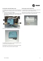
Page 59: ...E In the 0070 model the following servomotor is installed To manually move the valve use the hexagonal key and screw to open and unscrew to close Alternatively it is possible to remove the servomotor from the body of the valve and move the valve stem itself Servomotor and hot water valve To manually move the valve by turning the control knob clockwise to open and anti clockwise to close Alternativ...

Page 60: ...arm remove the cause and re set the safety thermostat C The hot water coil is not working 1 Check the hot water capacity and temperature 2 Check the function of the regulation valve see valve and servomotor D The hot gas coil is not working during dehumidification with re heat 1 Check the hot gas 3 way valve function 2 Check the function of the compressor serving the re heat See THE COMPRESSOR S D...

Page 61: ... and or sensors work properly PROBLEM POSSIBLE CAUSE CHECK CORRECTIVE ACTION ABSENT OR LOW AIR FLOW A There is no power to the fans Check the power supply to the fans B The air filters are clogged dirty filter alarm enabled 1 Shake the dust out of the cartridge and clean with a vacuum cleaner Replace the filter if it is completely blocked 2 Check the correct setting of the dirty filter pressure sw...

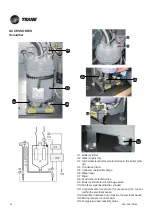
Page 62: ...arge discharge U6 Water input U7 Drain U8 Feed water solenoid valve U9 Boiler cylinder electric drainage valve U10 Overflow pipe behind the cylinder U11 Amperometric transformer for measuring the current within the electrical panel U12 Humidifier interface board inside the electrical panel U13 Microprocessor control board U14 Temperature and humidity probe U7 U4 U9 U5 U1 U8 U2 ...

Page 63: ...pply in order to maintain the optimum concentration of dissolved salts in the water in the cylinder U1 Feed water Values for the feed water for medium high level of conductibility of a humidifier with immersed electrodes Connections The installation of the humidifier requires connection to the feed tubes of the water drain 1 Values dependent on the specific conductibility in general TDS 0 93 s20 R...

Page 64: ...ctrodes unclip the cylinder fixing strap pull the cylinder upwards The boiler cylinder can be used many times after the electrodes are cleaned however it will eventually require replacement when the electrode meshes are too worn out to make further cleaning worthwhile The spare part consists of only the cylinder itself with the filter inside FEED AND DRAIN CONNECTIONS Periodic inspections of the f...

Page 65: ...ir temperature at set point Therefore the heating power installed is able to maintain the dry bulb temperature in the room during the dehumidification process TSR and TSRA heaters safety thermostats are fixed on the external edges of the electrical panel In position A for UPFLOW models In position B for DOWNFLOW models STANDARD CAPACITY V No kW OA 1105 1106 0070 400 3 50 2 6 8 7 2107 2207 2109 010...

Page 66: ...high power absorption 2 kW RED wire standard The wires of each element are connected to the CR1 and CR2 connectors on the electrical panel in such a way as to balance the load across the phases and create three stages of heating refer to the electric diagram on the side of the machine Temperature and humidity sensor The diagram shows an optional temperature and humidity sensor When replacing the s...

Page 67: ... the fresh air filter to the nearest external air inlet with a flexible hose which has a diameter of 100mm and secure the hose to the fresh air intake with a fastening collar The connection from the unit to the external air inlet must have the shortest and straightest path possible Unit EDC 0070 Unit EUC 0070 Unit EDC 0100 0250 Unit EUC 0100 0250 ...

Page 68: ...PKG SVX19B E4 68 Maintenance Clean using a blast of compressed air or replace the fresh air intake filters periodically Unit EDA EDW 1105 1106 Unit EUA EUW 1105 1106 ...

Page 69: ... threshold value The sensor is connected to the microprocessor control system as described in the electrical diagram of the unit The sensor has a temperature range of 50 C and 50 C and a protection level of IP67 it can be installed outside the unit by means of a cable which is 3 metres long A minimum distance of 2 metres is advisable from the unit discharge as shown in the diagram for upflow units...

Page 70: ...PKG SVX19B E4 70 ...

Page 71: ...71 PKG SVX19B E4 ...

Page 72: ...rtfolio of advanced controls and HVAC systems comprehensive building services and parts For more information visit www Trane com Trane has a policy of continuous product and product data improvement and reserves the right to change design and specifications without notice 2012 Trane All rights reserved PKG SVX19B E4 April 2012 We are committed to using environmentally conscious print practices tha...

Reviews: