ONLY DIPSWITCH
1 ON **
ONLY DIPSWITCH
2 ON
ONLY DIPSWITCH
3 ON
LOWER *
MIDDLE
UPPER
55
194
195
199
60
208
210
215
65
224
227
232
70
242
246
250
75
260
265
270
80
280
286
291
85
301
308
313
90
324
331
337
95
348
356
362
100
373
382
388
105
399
409
416
110
427
438
445
115
456
467
475
120
486
498
507
125
517
531
540
** With AM7 or AM8: Dip switch 1 = 10° of subcooling at 95° ambient
PRINTED FROM D155859P02 REV 4
3 TON HP R410A REFRIGERANT CHARGING CHART
* Data is based on 11.5° of subcooling at a 95° ambient
LIQUID GAGE PRESSURE (PSIG)
Liquid
Temp (°F)
3
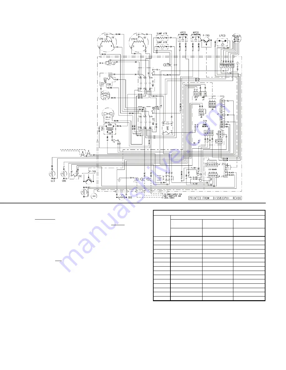
WIRING DIAGRAM
MANUAL CHARGING OR CHARGE ASSIST
TM
METHOD IN
COOLING
BETWEEN 55°F AND 120°F OD AMBIENT
It is recommended to install manufacturer approved matched indoor and
outdoor systems.
All approved split systems are AHRI rated with only TXV indoor systems.
The benefits of installing approved indoor and outdoor split systems are
maxi mum efficiency, optimum performance and the best overall system
reliability. The following charging methods are therefore prescribed for
matched systems with indoor TXVs.
1. Subcooling using the R-410A Refrigerant Charging Chart (in the cooling
mode) is the only recommended method of charging between 55°F and
120°F ambient temperatures.
2. When charging for ambient temperatures above 120°F, charge to 10°
subcooling. It is important to return when outdoor ambient temperature
is between 55°F and 120°F to verify system charge per these instruc-
tions.
3. For best results – the indoor temperature should be kept between 70°F
to 80°F. Add system heat if needed.
4. At startup, or whenever charge is removed or added, the system must
be operated for a minimum twenty (20) minutes to stabilize before
accurate measurements can be made. (Feature of Charge Assist™)
5. Measure Liquid Line Temperature and Refrigerant Pressure at service
valves. (Not required with Charge Assist.™)
6. Determine total refrigerant line length, and height (lift) if indoor section is above the condenser. Set dip switches on Charge Assist™ board as
indicated in the Subcool Charging Corrections Table on page 2 .
7. Locate your liquid line temperature in the left column of the table, and the intersecting liquid line gage pressure under the DIPSWITCH selection
column. Add refrigerant to raise the pressure to match the table, or remove refrigerant to lower the pressure. For manual charging, always wait twen-
ty (20) minutes for the system conditions to stabilize before adjusting charge again. (Not required with Charge Assist.™)
8. Charge Assist port is designed for liquid refrigerant charging.
9. When system is correctly charged, you can refer to System Pressure Curves (on page 8) to verify typical performance.


