background image

23

11

UNT-PRC002-GB

Sound power levels

Discharge

Measurement conditions:
Measurements taken in a room adjacent to the room containing the FWD, at the outlet of the rectangular duct (1.5 m
long) fixed to its discharge opening.

Fan

Power level in dB(A), per Hz frequency band

Overall power

Unit

speed

125

250

500

1000

2000

4000

8000

dB(A)

1

55

50

42

37

37

31

30

46

FWD 08

2

57

54

47

40

30

38

40

50

3

58

57

50

42

32

40

43

53

1

57

51

45

42

34

33

28

48

FWD 10

2

58

54

48

45

38

39

35

51

3

60

58

50

48

40

42

39

54

1

57

51

45

42

34

33

28

48

FWD 12

2

58

54

48

45

38

39

35

51

3

60

58

50

48

40

42

39

54

1

56

62

50

48

39

38

36

56

FWD 14

2

61

66

55

53

47

46

45

60

3

63

69

58

56

50

50

49

63

1

57

63

51

49

40

39

37

57

FWD 20

2

61

66

55

53

47

46

45

60

3

63

69

58

56

50

50

49

63

Intake

Measurement conditions:
Measurements taken at the horizontal air intake.

Fan

Power level in dB(A), per Hz frequency band

Overall power

Unit

speed

125

250

500

1000

2000

4000

8000

dB(A)

1

56

55

55

53

46

45

42

57

FWD 08

2

63

62

60

60

53

53

53

64

3

66

65

63

62

56

55

57

67

1

62

58

55

58

51

48

44

61

FWD 10

2

66

63

60

62

56

55

52

66

3

70

67

63

65

59

59

57

69

1

62

58

55

58

51

48

44

61

FWD 12

2

66

63

60

62

56

55

52

66

3

70

67

63

65

59

59

57

69

1

66

65

65

65

57

50

46

68

FWD 14

2

73

72

69

71

64

59

57

74

3

78

76

73

75

69

64

63

78

1

68

72

64

64

56

52

50

69

FWD 20

2

76

76

68

71

65

61

61

75

3

78

79

71

74

69

66

66

78

AH-SVX03C-GB

Vibration isolators 


…

Check that vibration isolators are free to operate and that there is no contact existing between the fan/motor 
chassis and the support.

Frequency inverter

1.  The VFD must be compatible with HVAC applications, such as fans with quadratic torque.
2.  The electric power output of the VFD shall be compatible with the nominal power of the motor.
3.  The VFD shall be compatible with its environment (IP rate, type of ventilation, ambient temperature, 

electromagnetic environment…)

4.  All recommendations indicated in the Installation/Operation/Maintenance manual of the VFD manufacturer must 

be respected.

5.  The VFD comes with default values which may have to be fine- tuned during commissioning.

CAUTION!

In some cases, mechanical issues my affect the fan or motor, and may be caused by the inverter settings (vibration, 
excessive noise, lower efficiencies, motor overheating…). If the inverter is removed and the mechanical issues do 
not persist, the inverter settings must be reconfigured. Inverter settings to verify can include: attenuated resonance, 
quadratic torque, frequency regulation, etc.

Unit connections


…

All electrical, water, and duct work connections of the unit must be completed by a qualified person. 


…

Check that electrical connections comply with the wiring diagram and that the thermal protection is operational. 


…

Completely stress-free connections are essential. 


…

The pipe work of the coils should be arranged to facilitate easy removal of the coil for maintenance purposes.

Coils


…

Check that the coil connections and valves are not leaking. If there are leaks, rectify the problem. 


…

Cooling coil sections are fitted with condensate drains. Check that these are properly fitted to allow draining and 
avoid air suction and water carry-over.

Water coil filling

In general, heating and cooling coils are filled with water and standard additives to protect against freezing and 
corrosion:
•  open the air vent
•  slightly open the water supply valve so that the heater battery fills slowly. This avoids thermal stress
•  as soon as the heater coil is full, close the air vent
•  open the water valve fully and switch on the fan
•  finally, the entire piping system must be completely vented.

Steam coil filling

•  Open gradually the air vent and drain valve on the condensate drain
•  Slightly open the steam valve until steam penetrates through the condensate drain valve and air vent
•  Close the condensate drain valve and air vent and open the steam valve fully
•  Vent regularly during operations

CAUTION!

 If the installation is switched off temporarily, condensate must not be stopped temporarily to remain in 

the pipes to avoid freezing and corrosion risk. 
For steam, overheated, high temperature coils, to prevent overheating inside the unit, the fan stop must be delayed 
by 3 to 5 minutes after the steam valve have been closed.

Electrical heaters

Electric air heaters are provided with automatic and/or manual reset overheat thermostats.

CAUTION!

 To prevent over heating inside the unit when the heater is being switched off, the fan maybe switched off 

after an over run period of 3 to 5 minutes.
The same shall be done when the unit is installed any other type of high temperature source.

Commissioning procedure

Summary of Contents for CLCF Climate Changer

Page 1: ...AH SVX03C GB CLCF Climate Changer Air Handling Units February 2021 Confidential and proprietaryTrane information Original instructions ...

Page 2: ... 450 650 Shipped unit dimensions Width x Depth mm 933 x 644 1133 x 754 1333 x 864 1333 x 1008 1333 1133 Height mm 260 310 360 460 660 Weight kg 32 46 61 76 118 Colour galvanised steel Recommended fuse size Unit alone aM gI A 8 16 8 16 8 16 8 25 8 25 Unit with electric heater gI A 16 2kW 25 4kW 40 230V 3 16 400V 3 20 3 25 3 25 1 Conditions Water entering leaving temperature 7 12 C Air inlet tempera...

Page 3: ...at the horizontal air intake Fan Power level in dB A per Hz frequency band Overall power Unit speed 125 250 500 1000 2000 4000 8000 dB A 1 56 55 55 53 46 45 42 57 FWD 08 2 63 62 60 60 53 53 53 64 3 66 65 63 62 56 55 57 67 1 62 58 55 58 51 48 44 61 FWD 10 2 66 63 60 62 56 55 52 66 3 70 67 63 65 59 59 57 69 1 62 58 55 58 51 48 44 61 FWD 12 2 66 63 60 62 56 55 52 66 3 70 67 63 65 59 59 57 69 1 66 65 ...

Page 4: ...instructions are given as a guide to good practice in the installation start up operation and maintenance by the user ofTrane CLCF Air Handling Units They do not contain full service procedures necessary for the continued successful operation of this equipment The services of a qualified technician should be employed through the medium of a maintenance contract with a reputable service company Rea...

Page 5: ...nel 5 For inspection on the Air Handling Units and to avoid risks the units surroundings are to be sufficiently lighted 6 Any components which contain refrigerant shall be handled only by Authorized personnel The refrigerant shall be always recovered before any intervention on such component or before the end of life of equipment The recovered refrigerant shall be disposed accordingly Any componen...

Page 6: ... refrigerant with a temperature below than 2 C The unit controls should be designed in order to protect the exchanger against freezing Trane cannot be held responsible for damages coming from freezing de freezing operation Electrical motors Electrical motors are factory tested and properly run when leaving the factory Any wiring faults on motors will cause damage for whichTrane cannot be held resp...

Page 7: ... 57 69 1 66 65 65 65 57 50 46 68 FWD 14 2 73 72 69 71 64 59 57 74 3 78 76 73 75 69 64 63 78 1 68 72 64 64 56 52 50 69 FWD 20 2 76 76 68 71 65 61 61 75 3 78 79 71 74 69 66 66 78 AH SVX03C GB Maintenance contract It is strongly recommended that you sign a maintenance contract with your local Service Agency This contract providesTrane regular maintenance of your installation by a specialist in our eq...

Page 8: ...eater gI A 16 2kW 25 4kW 40 230V 3 16 400V 3 20 3 25 3 25 1 Conditions Water entering leaving temperature 7 12 C Air inlet temperature 27 19 C DB WB Nominal air flow 2 Conditions Water entering leaving temperature 50 45 C Air inlet temperature 20 C DB Nominal air flow 3 At high speed with nominal air flow 4 Water entering leaving temperature 90 70 C air inlet temperature 20 C DB Nominal air flow 5...

Page 9: ...pacity vertical of each sling and spreader bar should be no less than the shipping weight 4 The unit must be lifted with care avoiding shock load by lifting the unit slowly and evenly 5 All lifting points in one axis of the unit must be used when offloading and moving the unit 6 Belts are to be provided by the rigger and attached to all lifting points CAUTION Loading unloading and removal of singl...

Page 10: ...the presence of an electrical cabinet for instance one of the following junction systems can be used depending on the unit configuration On the casing nylon or aluminium angles are positioned on the inside or outside of each section Pull together the unit sections ensuring that the nylon or aluminium angles fit with the angles of the adjoining section Secure the assembly with bolts If a technical ...

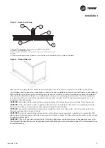
Page 11: ...f protrudes 20 mm on each side of the unit 4 Panel 5 Factory installed gasket to be covered by a layer of Silicone not supplied byTrane for outdoor installation Figure 4 Fixing of the unit Remove the mounting vibrator blocks before starting the unit They are just used to ensure safe transportation To minimize noise transmission depending on the site location additional insulation material such as ...

Page 12: ...5 Unit with electric heater gI A 16 2kW 25 4kW 40 230V 3 16 400V 3 20 3 25 3 25 1 Conditions Water entering leaving temperature 7 12 C Air inlet temperature 27 19 C DB WB Nominal air flow 2 Conditions Water entering leaving temperature 50 45 C Air inlet temperature 20 C DB Nominal air flow 3 At high speed with nominal air flow 4 Water entering leaving temperature 90 70 C air inlet temperature 20 C...

Page 13: ...ower level in dB A per Hz frequency band Overall power Unit speed 125 250 500 1000 2000 4000 8000 dB A 1 56 55 55 53 46 45 42 57 FWD 08 2 63 62 60 60 53 53 53 64 3 66 65 63 62 56 55 57 67 1 62 58 55 58 51 48 44 61 FWD 10 2 66 63 60 62 56 55 52 66 3 70 67 63 65 59 59 57 69 1 62 58 55 58 51 48 44 61 FWD 12 2 66 63 60 62 56 55 52 66 3 70 67 63 65 59 59 57 69 1 66 65 65 65 57 50 46 68 FWD 14 2 73 72 6...

Page 14: ...ee To avoid noise transmission the fitting of an intermediate flexible connection of at least 140 mm depth between duct work and the unit is recommended This should be unstressed when initially positioned To ensure the best possible performance of the units whilst avoiding excessive pressure loss in the duct system and minimizing air stream noise compliance with good practice in duct assembly and ...

Page 15: ... ground the unit use a bolt already on the unit or screw it onto the base The operator safety can be ensured by either a belt guard or a factory mounted micro switch on the fan section door The electrical connection of this micro switch made by the contactor will cut off the electrical feeding to the motor and stop the fan motor group when the door of the fan section is opened Motor connection As ...

Page 16: ...teel Recommended fuse size Unit alone aM gI A 8 16 8 16 8 16 8 25 8 25 Unit with electric heater gI A 16 2kW 25 4kW 40 230V 3 16 400V 3 20 3 25 3 25 1 Conditions Water entering leaving temperature 7 12 C Air inlet temperature 27 19 C DB WB Nominal air flow 2 Conditions Water entering leaving temperature 50 45 C Air inlet temperature 20 C DB Nominal air flow 3 At high speed with nominal air flow 4 ...

Page 17: ...e access To access the Frostat frame if present it is necessary to remove the small side panel provided with a handle see Figure 10 Remove the black gasket placed around the frostat frame Remove the screws that fix the panel Using the handle remove the frostat panel Access the frostat frame sliding it on the side of the unit Figure 10 Frostat frame access 1 Panel gasket 2 Screws 3 Frostat panel wi...

Page 18: ...inlet temperature 20 C DB Nominal air flow 5 A rectangular glass wool duct 1m50 long is placed on the blower The measurement is taken in the room containing the blower unit Heat exchanger operating limits FWD water temperature max 100 C absolute service pressure min 1 bar max 11 bars Accessories Hot water coil water temperature min 2 C max 100 C absolute service pressure min 1 bar max 11 bars AH S...

Page 19: ...igures 14 17 it is important to note that 1 The cooling coil sections and the evaporative or honeycomb humidifier sections without recirculating pump are equipped with a condensate drain pipe Item 1 Figure 14 A B 2 For evaporative humidifier sections equipped with are circulation pump the drain pipe used typically for cleaning purposes item 3 Figure 16 A B needs to be connected to a shut off valve...

Page 20: ...aving temperature 7 12 C Air inlet temperature 27 19 C DB WB Nominal air flow 2 Conditions Water entering leaving temperature 50 45 C Air inlet temperature 20 C DB Nominal air flow 3 At high speed with nominal air flow 4 Water entering leaving temperature 90 70 C air inlet temperature 20 C DB Nominal air flow 5 A rectangular glass wool duct 1m50 long is placed on the blower The measurement is take...

Page 21: ...2 61 66 55 53 47 46 45 60 3 63 69 58 56 50 50 49 63 Intake Measurement conditions Measurements taken at the horizontal air intake Fan Power level in dB A per Hz frequency band Overall power Unit speed 125 250 500 1000 2000 4000 8000 dB A 1 56 55 55 53 46 45 42 57 FWD 08 2 63 62 60 60 53 53 53 64 3 66 65 63 62 56 55 57 67 1 62 58 55 58 51 48 44 61 FWD 10 2 66 63 60 62 56 55 52 66 3 70 67 63 65 59 5...

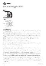
Page 22: ...absolute service pressure min 1 bar max 11 bars AH SVX03C GB Figure 18 Figure 19 Pre start checklist Initially the complete unit and all components should be thoroughly cleaned and all dust and other deposits completely removed The unit must be maintained in a clean condition Prior to dispatch each unit is thoroughly checked Nevertheless as part of the commissioning procedure it is imperative to r...
Page 23: ...erter settings vibration excessive noise lower efficiencies motor overheating If the inverter is removed and the mechanical issues do not persist the inverter settings must be reconfigured Inverter settings to verify can include attenuated resonance quadratic torque frequency regulation etc Unit connections All electrical water and duct work connections of the unit must be completed by a qualified...

Page 24: ...that the entering air side of the filter is exposed to the contaminated air stream Refer to the certified submittals which maybe different If roll filters are used check that the filter unit drive motor and the switch control are working correctly Humidifiers The evaporative humidifiers with or without recirculating pump are provided with a water flow control valve During fan operation with the do...

Page 25: ...ease the air volume by changing or adjusting the belt drive pulleys Please contact your localTrane sales office to get a proper belt drive selection CAUTION Do not increase the fan speed beyond the motor power rating allowed limit CAUTION Increasing the fan speed should be done only after a careful study of the operating point on the appropriate fan curve Contact your localTrane sales office for a...

Page 26: ...s Hot water coil water temperature min 2 C max 100 C absolute service pressure min 1 bar max 11 bars AH SVX03C GB The regulating valve in the pressure side must be adjusted to the correct water quantity The water purging volume should be roughly equivalent to the amount of water evaporated from the system On request we will advise you in choosing the suitable volume Check the correct setting with ...

Page 27: ... Module Plus can be selected This includes all the standard CCM features with the addition of Power Wiring A Starter Panel and the installation of a Free Issued Controller compatible with the BMS is to be installed If a different control is installed please refer to its user guide or manual Shipping The controls enclosure will normally be factory fitted on the fan section of the air handling unit ...

Page 28: ...ned cable to the control panel One pair supplies power to the device and the other is the pressure signal from the device to the controller Outside temperature sensor The outside temperature sensor should be mounted on a Northfacing wall It requires a single pair of screened wires The sensor can be factory mounted in the fresh air inlet Other items are supplied loose on a project specific basis an...

Page 29: ...mpressor start or run capacitors to discharge ForTrane provided variable frequency drives wait 20 minutes For other manufacturer s variable frequency drives or energy storing components refer to the appropriate manufacturer s literature for allowable waiting periods for discharge of capacitors Verify with an appropriate voltmeter that all capacitors are discharged Failure to disconnect power and o...

Page 30: ... temperature 50 45 C Air inlet temperature 20 C DB Nominal air flow 3 At high speed with nominal air flow 4 Water entering leaving temperature 90 70 C air inlet temperature 20 C DB Nominal air flow 5 A rectangular glass wool duct 1m50 long is placed on the blower The measurement is taken in the room containing the blower unit Heat exchanger operating limits FWD water temperature max 100 C absolute...

Page 31: ...ponsibility for system cleaning Fan and motor Long term storage 3 months of a fan motor assembly may cause damage to the bearings brinelling in case of long term storage it is necessary to turn the fan wheel from time to time Every six months Check for soiling damage corrosion and any tendency to bind and clean as necessary Touch up any spot damage to the unit casing and the fan impeller using a z...

Page 32: ... fuse size Unit alone aM gI A 8 16 8 16 8 16 8 25 8 25 Unit with electric heater gI A 16 2kW 25 4kW 40 230V 3 16 400V 3 20 3 25 3 25 1 Conditions Water entering leaving temperature 7 12 C Air inlet temperature 27 19 C DB WB Nominal air flow 2 Conditions Water entering leaving temperature 50 45 C Air inlet temperature 20 C DB Nominal air flow 3 At high speed with nominal air flow 4 Water entering l...

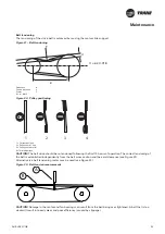
Page 33: ...3 66 65 63 62 56 55 57 67 1 62 58 55 58 51 48 44 61 FWD 10 2 66 63 60 62 56 55 52 66 3 70 67 63 65 59 59 57 69 1 62 58 55 58 51 48 44 61 FWD 12 2 66 63 60 62 56 55 52 66 3 70 67 63 65 59 59 57 69 1 66 65 65 65 57 50 46 68 FWD 14 2 73 72 69 71 64 59 57 74 3 78 76 73 75 69 64 63 78 1 68 72 64 64 56 52 50 69 FWD 20 2 76 76 68 71 65 61 61 75 3 78 79 71 74 69 66 66 78 AH SVX03C GB Belt tensioning The t...

Page 34: ...s recommended to use a metal ruler instead of a string Correct position is showed on Figure 24 Figure 24 Pulley alignment Pulley removal Pulleys are generally mounted with a conic joint To remove pulleys follow the manufacturer s directions Pulleys not provided with a conic joint are mounted by forcing them onto the shaft To remove them heat the pulley hub and use a pulley extractor Belt replaceme...

Page 35: ...ume and performance change WARNING If a damper or intake discharge hole is positioned on the bottom panel and the section is equipped with inspection access safety devices must be provided to cover the damper hole when entering in the section Note It is recommended to install the gauge or the differential pressure switch if necessary with a visible indicating light to have a constant control over ...

Page 36: ...orrectly and that the water level is correct Adjust as necessary Depending upon the extent of water contamination the degree of hardness and water treatment any scale deposits or other impurities must be cleaned off from the air washers Any severe calcium deposits on components such as spray pipes droplet separators or strainers indicate that the treatment is inadequate Deposits on spray pipes str...

Page 37: ... deposits must be removed Make sure the bypass damper if any is operating properly If a bypass damper is fitted maintain as suggested in above Dampers section Heat wheel Refer to the manufacturer s instructions for proper maintenance of the wheel wheel drive and motor The construction of the matrix is such that it is virtually completely self cleaning The rotor may be cleaned with pressurised air ...

Page 38: ...0 45 C Air inlet temperature 20 C DB Nominal air flow 3 At high speed with nominal air flow 4 Water entering leaving temperature 90 70 C air inlet temperature 20 C DB Nominal air flow 5 A rectangular glass wool duct 1m50 long is placed on the blower The measurement is taken in the room containing the blower unit Heat exchanger operating limits FWD water temperature max 100 C absolute service press...

Page 39: ... 50 48 39 38 36 56 FWD 14 2 61 66 55 53 47 46 45 60 3 63 69 58 56 50 50 49 63 1 57 63 51 49 40 39 37 57 FWD 20 2 61 66 55 53 47 46 45 60 3 63 69 58 56 50 50 49 63 Intake Measurement conditions Measurements taken at the horizontal air intake Fan Power level in dB A per Hz frequency band Overall power Unit speed 125 250 500 1000 2000 4000 8000 dB A 1 56 55 55 53 46 45 42 57 FWD 08 2 63 62 60 60 53 5...

Page 40: ...rmation please visit trane com or tranetechnologies com Trane has a policy of continuous product and product data improvement and reserves the right to change design and specifications without notice We are committed to using environmentally conscious print practices 2021Trane AH SVX03C GB February 2021 Supersedes AH SVX03B_0114 Confidential and proprietaryTrane information ...

Reviews: