ARTC-SVX001B-EN
29
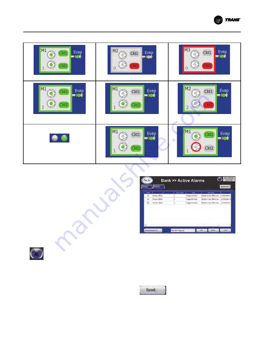
Table 3. Module status conditions
Module is available
Module is unavailable
Module turned off by alarm and unavailable
Refrigeration circuit in normal state;
Compressor ON
Refrigeration circuit is non-operational;
Compressor OFF
Refrigeration circuit in alarm state;
compressor OFF
Isolation Valves:
- Valve LED is green = valve is open
- Valve LED is gray = valve is closed
Compressor 1 is OFF; Compressor 2 is ON
Compressor 1 is ON; Compressor 2 is in alarm
Active Alarms Screen
The active alarms screen lists all active (triggered) and
non-active alarms in tabular form. See following figure.
Information presented in this screen in tabular form
includes:
•
Alarm is considered 'Active' (Triggered) if 'Source
Value' = 1, other words it's still active in the PLC.
•
If alarm is 'Not Active' (Not Triggered), its 'Source
Value' = 0 and it can be reset using Reset button.
•
Both 'Active' and 'Not Active' alarms can be
acknowledged. When 'Not Active' alarm is
acknowledged, it can be reset, which will remove it
from the list, so only 'Active' alarms will remain on
the list.
Select
This column indicates if the alarm is selected or
unselected for acknowledgment or resetting.
ID
This column displays the descriptive title each alarm.
Figure 16.
Active alarms for the chiller
Source Value
This column displays the numeric value of each alarm.
If an alarm has a Source Value = 1, it can only be reset
with the RESET button when the condition triggering
the alarm has been resolved.
If an alarm has a Source Value = 0, it can be
acknowledged or reset, which removes it from the
active alarms list.
State
This column displays the alarm state. There are four
possible states for any alarm:


