background image

AFDG/AFDU Startup Procedure

AFDG-SVU01L-EN

35 

Note:

If the set values do not match, contact the 
local Trane Service agency first, or, the 
La Crosse Business Unit Technical Service 
Department. The correct values are listed 
on the unit nameplate shipped with each 
unit.

5. In order to view the AFDG/AFDU configurable settings, 

go to the Chiller Configuration tab in the Tracer® TU 
service tool and select the AFD expanding section.

6. If the drive LLID is not found or if it is necessary to re-

bind the drive LLID, follow the procedure below.

a. The drive’s main DC bus must be charged in order 

for the drive LLID to be recognized or bound. Close 
the drive disconnect and apply line power to the 
drive. 

b. With a laptop connected to the chiller and with 

Tracer® TU running, enter the binding view menu 
of Tracer® TU and locate the “Starter” LLID in the 
menu. Select the “Bind” button for the AFD Starter 
LLID.

c. The screen “Is the device alone selected?” displays. 

In the AFD, wave magnet on the LLID and light the 
“service” LED. 

d. On the Tracer® TU screen, select the “yes” button 

to indicate the LLID has been selected. 

e. When properly bound, exit the binding view.

f. Perform any remaining startup items.

7. When ready, start the drive from the Tracer® 

AdaptiView™ display.

8. Check the AFDG/AFDU chiller drive response to the 

UC800. Initially, the drive will go to 38 hertz and stay 
there until the CenTraVac™ chiller vanes open based 
on load. The drive will change the speed from there 
based on load demand.

9. Document all information on the Startup log.

Drive Settings

Set the values in the order shown in 

Table 10

 based on 

information obtained from the chiller nameplate.

For additional information, refer to the programming 
manual that is shipped with the drive. The programming 
manual includes a detailed section that discusses 
accessing the parameters in the drive.

This process is summarized briefly below:

1. To access the parameters, press the 

Main Menu

 key.

2. If required, enter the password (

999

).

3. To select a parameter group, use the up/down arrow 

keys to highlight the parameter group, and then press 
the 

Enter

 key to access that group.

4. Use the up/down arrow keys to access the parameter 

number, and then press the 

OK

 key. 

5. Use the up/down arrow keys to change the parameter, 

and then press the 

OK

 key to change the setting.

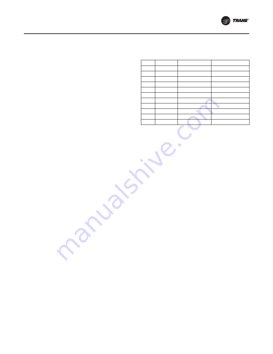
Table 10. Job specific settings

Group Parameter Description

Value

1

20

Motor kW

Set to nameplate CPKW

1

22

Motor voltage

Nameplate voltage

1

24

Motor current

Set to nameplate TVA

1

25

Motor nominal speed Set to nameplate TRPM

1

30

Stator resistance

Set to nameplate SRES

1

35

Main reactance

Set to nameplate MGRE

4

16

Torque limit mode

Set to maximum

4

18

Current limit

Set to maximum

8

(a)

(a) If the customer is connecting to the remote-mounted AFDG with MOD-

BUS®, Group 8 parameters MUST be selected.

01

Control site

1

8

(a)

02

Control word source 0

8

(a)

53

Start select

0

6. If the chiller does not start, re-enter the motor kW, 

voltage, and current. The stator resistance and main 
reactance values will change based on the motor table 
look up that is built into the drive. 

If the motor still will 

not start,

 then perform an AMA (the AMA will 

physically measure the stator resistance and main 
reactance values, including the connecting cables 
between the drive and the motor; the values will then 
be set in the drive when the AMA is complete).

To perform an AMA:

a. Change the following parameters:

0-40 Hand on key; set to enable.

0-41 Off key; set to enable.

5-12 Terminal 27 digital input; set to 0, no 
function.

b. Go to parameter 1-29 automatic motor adaptation 

(AMA) and enter 1 to enable complete AMA.

c. Press the hand key “on” to start the AMA. The 

display should now begin to show the steps 
completing; there are approximately 16 steps that 
need to be completed. If the drive displays an Alarm 
53, change the motor voltage value in parameter 
1-22 (for example, change from 460 volt to 480 volt 
or visa versa) and then try running the AMA again.

d. After the AMA is finished, the display will read 

“Press OK to finish AMA.” Press 

OK

.

Important:

After the AMA is finished, set parameters 
0-40, 0-41, 5-12, and 1-29 back to their 
original settings.

7. If the drive is still having difficulty starting the motor, it 

may be necessary to perform a reset on the drive; this 
procedure will reset the drive parameters back to the 
original Danfoss defaults. After this has been 
completed, first set the parameters i

Table 11

 and 

then set the values in 

Table 10

.

Summary of Contents for AFDG

Page 1: ...all and service the equipment The installation starting up and servicing of heating ventilating and air conditioning equipment can be hazardous and requires specific knowledge and training Improperly...

Page 2: ...ent that is used in these service procedures In addition some states or municipalities may have additional requirements that must also be adhered to for responsible management of refrigerants Know the...

Page 3: ...t damage System contains oil and refrigerant and may be under positive pressure Recover refrigerant to relieve pressure before opening the system See unit nameplate for refrigerant type Do not use non...

Page 4: ...binet Wire Routing 19 Wire Routing 19 Wire Sizing 20 Grounding the Cabinet 20 UC800 AFD Operation 25 Adaptive Frequency Drive Control 25 Introduction 25 Chiller and AFD Sequence of Operation 25 Compre...

Page 5: ...mote disconnects and discharge all motor start run capacitors before servicing Follow proper lockout tagout procedures to ensure the power cannot be inadvertently energized For variable frequency driv...

Page 6: ...ment could result in death or serious injury Safety Precautions 1 This equipment should be adjusted and serviced by qualified electrical maintenance personnel familiar with the construction and operat...

Page 7: ...tors Failure to disconnect power and discharge capacitors before servicing could result in death or serious injury Disconnect all electric power including remote disconnects and discharge all motor st...

Page 8: ...ransistors that turn on and off in response to the gate driver A combination of two distinct operating modes make up the AFDG AFDU control within the chiller s UC800 control First by controlling the i...

Page 9: ...quirement on SSRLs of 730 780 850 890 945 and 1050 F0 Drive Bus Bars on SSRLs of 730 780 850 890 945 and 1050 G0 D Drive Module on SRRLs of 190 240 302 361 and 443 at 460V and 155 192 242 290 344 and...

Page 10: ...nce AA Original Design of Tracer AdaptiView Chiller Control with TR200 Drive Digit 12 Starter Type A Unit Mounted Digit 13 Agency Listing 0 UL and CUL Listed Standard on All Units Digit 14 Special Opt...

Page 11: ...sure is installed away from oil coolants or other airborne contaminants Do not install the drive above 3300 feet 1000 meters without derating output power For every 3300 feet 1000 meters above 3300 fe...

Page 12: ...RONT VIEW 1 400 18 660 RECOMMENDED MOUNTING HOLES 2 580 3 28 17 30 1 400 23 74 18 700 2 580 3 760 3 760 23 82 VIEW A A 23 42 MAX DOOR OPENING 23 42 MAX DOOR OPENING 109 MAX DOOR SWING 109 MAX DOOR SWI...

Page 13: ...D 13 92 12 28 6 50 4 84 5X MAGNETIC CORE CHOKES A BOTTOM VIEW 17 30 25 04 3 35 1 400 2 580 1 400 2 580 3 760 3 760 23 82 6 50 14 05 3 740 3 23 25 04 63 24 31 62 31 62 1 280 1 280 2 470 2 470 3 740 1 4...

Page 14: ...8 43 T1 10 10 GND 16 90 MIN 22 50 MAX L1 L2 L3 2X1 TERMINAL STRIP 11 73 TOP VIEW 1 85 3 90 9 10 12 80 2 80 7 90 1 88 7 90 2 80 15 60 120VAC CONTROL LOW VOLTAGE WIRING 126 22 2 50 18 74 2 50 18 86 6 54...

Page 15: ...N 22 50 MAX L1 L2 L3 11 73 2 91 2X1 TERMINAL STRIP 10 10 GND 18 43 T1 16 56 T2 14 69 T3 Adaptive Frequency Drive for Chillers 69 50 5 83 2X1 TERMINAL STRIP SERVICE ACCESS DOOR CIRCUIT BREAKER 1 13 30...

Page 16: ...osed and safely be contained within the starter enclosure However the components may sustain damage 1 57 3X 10 00 19 37 17 86 14 09 6 39 7 72 47 41 44 26 1 57 30 00 2 50 1 29 63 41 INDICATES CONDUCTOR...

Page 17: ...approximately 24 inches 61 cm to verify proper center of gravity lift point To avoid dropping of unit reposition lifting point if unit is not level Important AFDG remote mounted and AFDU unit mounted...

Page 18: ...eye Use of two chain hoists one for each lift eye or use of a single hoist with a spreader bar are permissible methods for lifting the drive Table 3 Drive weights for AFDU unit mounted Voltage Drive P...

Page 19: ...iring should be copper and should be sized according to applicable codes to handle the drive s continuous rated input current Refer to submittals for power lug sizes and location along with control wi...

Page 20: ...en the ground connections to 375 in lb 42 4 N m Note The AFDU unit mounted ships grounded to the chiller WARNING Proper Field Wiring and Grounding Required Failure to follow code could result in death...

Page 21: ...20 for drive component list Motor Leads CTs From 575V Line Local Control Panel LCP To Motor Input Power and Control Wiring AFDG SVU01L EN 21 Note Wiring from the drive to the motor is required to be r...

Page 22: ...n mode choke Figure 10 AFDG remote mounted open assembly no doors F4 Units F3 Units are similar but have only two inverters Input Power and Control Wiring 22 AFDG SVU01L EN Units with Ceramic bearings...

Page 23: ...Figure 11 AFDU unit mounted component layout Motor Leads Circuit Breaker Control Power Transformer Panel Cooling Fan Input Power and Control Wiring AFDG SVU01L EN 23...

Page 24: ...r Module AFD Starter Fault Speed Signal Drive Module Common Mode Choke CTs cal ntrol nel CP Units with ceramic bearings will not get common mode chokes Units with ceramic bearings will not get common...

Page 25: ...timal operating condition is found the algorithm can avoid the surge in the future When surge is detected a surge recovery routine makes adjustments to move out of surge reestablish stabile operating...

Page 26: ...he UC800 Startup The starting speed for AFD under UC800 control will vary depending upon the pressure ratio acrossthe compressor The UC800 predicts the condensing pressure during startup and sets the...

Page 27: ...ol algorithm will periodically readjust this boundary This re optimization will occur when any of three different criteria are met 1 After startup stabilization the control will re optimize unless the...

Page 28: ...the new surge boundary Surge Detection Surge detection control logic monitors changes in compressor motor current A surge occurrence leaves a characteristic motor current signature as shown in Figure...

Page 29: ...C800 to provide a speed reference to the drive The UC800 also provides both Fault and Up to Speed transition complete contact closure inputs for variable frequency drive starters At start of the compr...

Page 30: ...ommunication Potential Transformers Line Side of Starter Circuit Breaker Starter Module to Variable Speed Drive Interface HFC Stop Relay 2K11 2K1 2K1 Start Relay Starter Module 3 Phase Current Transfo...

Page 31: ...ion Potential Transformers Line Side of Starter Circuit Breaker Starter Module to Variable Speed Drive Interface HPC Stop Relay 2K11 2K1 2K1 Start Relay Starter Module 3 Phase Current Transformers Loa...

Page 32: ...o 60 active or historic alarms A technician can interact with an individual device or a group of devices for advanced troubleshooting For more information on Tracer TU visit your local Trane Service c...

Page 33: ...S Current Unbalance Trip Point 15 100 30 Percent Current Unbalance Grace Period 10 255 90 Seconds Maximum Acceleration Time 6 64 6 Seconds Set to 30 Acceleration Shutdown Action Shutdown Transition Sh...

Page 34: ...the power cannot be inadvertently energized For variable frequency drives or other energy storing components provided by Trane or others refer to the appropriate manufacturer s literature for allowab...

Page 35: ...Use the up down arrow keys to access the parameter number and then press the OK key 5 Use the up down arrow keys to change the parameter and then press the OK key to change the setting Table 10 Job sp...

Page 36: ...small Heat sink temp 1634 0 23 Display line 2 large Power Kw 1610 0 24 Display line 3 large Freq Hz 1613 0 40 Hand on key Disabled 0 0 41 Off key Disabled 0 0 60 Main Menu password 999 0 61 Access to...

Page 37: ...Data CT Meter Scale 0 RLA Stop Delay 3 KW Motor NP RLA Volts Hz Voltage Transformer Ratio 20 Prestart Checks Date Checked Current Unbalance Trip Point 30 Drive Grounded Acceleration Time 30 Motor Rot...

Page 38: ...terminal connections inside the drive enclosure Ensure all are clean and tight and not rubbing against each other anywhere WARNING Live Electrical Components Failure to follow all electrical safety pr...

Page 39: ...power including remote disconnects and discharge all motor start run capacitors before servicing Follow proper lockout tagout procedures to ensure the power cannot be inadvertently energized For varia...

Page 40: ...40 AFDG SVU01L EN Wiring Schematics For reference an as built schematic wiring diagram and a field wiring connection diagram are located inside the main control panel door of the chiller...

Page 41: ......

Page 42: ......

Page 43: ......

Page 44: ...are committed to using environmentally conscious print practices Trane by Trane Technologies NYSE TT a global climate innovator creates comfortable energy efficient indoor environments for commercial...

Reviews: