background image

18 

 18-BC77D1-6


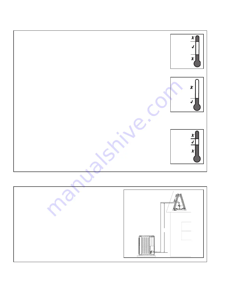
STEP 1 - Check the outdoor temperatures. 

Subcooling (in cooling mode) is the only recom-

mended method of charging above 55º F ambi-

ent outdoor temperature.  See Section 14.2.

For outdoor temperatures below 55º F, see Sec-
tion 14.3.

Note:

 It is important to return in the spring or 

summer to accurately charge the system in the 
cooling mode when outdoor ambient tempera-
ture is above 55º F.

For best results the indoor temperature should 

be kept between 70º F to 80º F.  

STEP 1 - Use the refrigerant line total length 
and lift measurements from Section 5.3.

Total Line Length = __________ Ft.

Vertical Change (Lift) = __________ Ft.

Section 14. System Charge Adjustment

14.1 Temperature Measurements

14.2 Subcooling Charging in Cooling (Above 55º F Outdoor Temp.)

LIFT

Indoor Temp

80º F

70º F

Outdoor Temp 1

55º F

120º F

Outdoor Temp 2

See Section 14.3 for 

Outdoor 

Temperatures 

Below 55º F

See Section 14.2 for 

Outdoor 

Temperatures 

Above 55º F

55º F

Summary of Contents for 4TWB4018G

Page 1: ...roved matched indoor and outdoor systems All of the manufacture s split systems are A H R I rated only with TXV EEV indoor systems Some of the benefits of installing approved matched indoor and outdoor split systems are maximum efficiency optimum performance and the best overall system reliability 4TWB4 Installer s Guide Table of Contents Section 1 Safety 2 Section 2 Unit Location Considerations 3...

Page 2: ... for component replacement For specific handling concerns with R 410A and POE oil reference Retrofit Bulletins SS APG006 EN and APP APG011 EN Extreme caution should be exercised when opening the Liquid Line Service Valve Turn counterclockwise until the valve stem just touches the rolled edge No torque is required Failure to follow this warning will result in abrupt release of system charge and may...

Page 3: ...ength of refrigerant lines from outdoor to indoor unit should NOT exceed sixty 60 feet 2 The maximum vertical change should not exceed sixty 60 feet 3 Service valve connection diameters are shown in Table 5 1 Note For line lengths greater than sixty 60 feet Refer to Refrigerant Piping Application Guide SS APG006 EN or Refrigerant Piping Software Program 32 3312 03 or latest revi sion 061 Heat Pump...

Page 4: ... Outdoor unit location must be far enough away from any structure to prevent excess roof runoff water or icicles from falling directly on the unit 2 4 Cold Climate Considerations NOTE It is recommended that these precau tions be taken for units being installed in areas where snow accumulation and prolonged below freezing temperatures occur Units should be elevated 3 12 inches above the pad or roof...

Page 5: ...east 1 larger than the unit on all sides The pad must be separate from any structure The pad must be level The pad should be high enough above grade to allow for drainage The pad location must comply with National State and Local codes For other applications refer to Application Guide SSC APG001 EN If installed within one mile of salt water including seacoasts and inland waterways models without f...

Page 6: ...ory Charge 5 4 Refrigerant Line Insulation Important The Vapor Line must always be insulated DO NOT allow the Liquid Line and Vapor Line to come in direct metal to metal contact Vapor Line Liquid Line Insulation Determine required line length and lift You will need this later in STEP 2 of Section 14 Total Line Length __________ Ft Total Vertical Change lift __________ Ft Trane outdoor condensing u...

Page 7: ... structure due to vibration transmission from the refrigerant lines For Example When the refrigerant lines have to be fastened to floor joists or other framing in a structure use isolation type hangers Isolation hangers should also be used when refrigerant lines are run in stud spaces or enclosed ceilings Where the refrigerant lines run through a wall or sill they should be insulated and isolated ...

Page 8: ... or other appropriate method every 8 ft 8 Feet Maximum Isolation Through Wall DO NOT hang line sets from ductwork Sealant Insulation Vapor Line Wall Ductwork Isolator Line Set Section 7 Refrigerant Line Brazing 7 1 Braze The Refrigerant Lines STEP 1 Remove caps or plugs Use a debur ing tool to debur the pipe ends Clean both internal and external surfaces of the tubing using an emery cloth ...

Page 9: ... avoid heat damage and continue the dry nitrogen purge Braze the refrigerant lines to the service valves Continue the dry nitrogen purge Do not re move the wet rag until all brazing is completed Important Remove the wet rag before stopping the dry nitrogen purge NOTE Precautions should be taken to avoid heat damage to basepan during brazing It is recommended to keep the flame directly off of the b...

Page 10: ...2 Check for leaks by using a soapy solu tion or bubbles at each brazed location Remove nitrogren pressure and repair any leaks before continuing Section 8 Refrigerant Line Leak Check 8 1 Check For Leaks STEP 1 Pressurize the refrigerant lines and evaporator coil to 150 PSIG using dry nitrogen 150 PSIG ...

Page 11: ...te blank off the vacuum pump and micron gauge and close the valves on the manifold gauge set 1 MIN Section 10 Service Valves 10 1 Open the Gas Service Valve 0350 Microns ON OFF CAP 1 4 TURN ONLY COUNTERCLOCKWISE FOR FULL OPEN POSITION VALVE STEM GAS LINE CONNECTION UNIT SIDE OF VALVE PRESSURE TAP PORT Important Leak check and evacuation must be completed before opening the service valves NOTE Do n...

Page 12: ...e System Service Port 3 16 Hex Wrench Unit Side of Service Valve Extreme caution should be exercised when opening the Liquid Line Service Valve Turn counterclockwise until the valve stem just touches the rolled edge No torque is required Failure to follow this warning will result in abrupt release of system charge and may result in personal injury and or property damage WARNING Section 11 Electric...

Page 13: ...k up Diagrams Air Handler Hook up Diagram Red Yellow Green White Blue Orange W1 O B X2 G Y1 Yellow Yellow Blue Orange Blue Black X2 Red Red Orange R Comfort Control Comm Variable Speed Furnace or Air Handler Heat Pump Black W1 W2 W3 G Y2 B O BK D Y1 R Neatly bundle all low voltage wires behind the service valve cover as shown Notes 1 See User Interface 24 V Mode setup menu for control mode and coo...

Page 14: ...dler Heat Pump Neatly bundle all low voltage wires behind the service valve cover as shown Field wiring Yellow Blue Black X2 Red Orange Red Yellow Orange Green White Blue B B Blue W X2 G Y1 Y1 Yellow R O O R B YI W1 YO DH BK G W2 W3 R Red O Orange In Out W1 White Variable Speed Furnace Hook up Diagram AM7 Air Handler Hook up Diagram 1 1 1 2 3 4 5 1 2 3 4 5 HP 2 Compressor 2 Stages AC System OUTDOO...

Page 15: ...at or below 30 F ambient See Service Facts shipped in the outdoor unit for more information Pin Identification See Illustration at right 1 TEST_COMMON Shorting any of the other pins to this pin causes the function of the other pin to be executed Leaving this pin open results in the normal mode of operation 2 TST Test Shorting TEST_COMMON to this pin speeds up all defrost board timings 3 FRC_DFT Fo...

Page 16: ...h Voltage Ground Ground the outdoor unit per national state and local code requirements LIVE ELECTRICAL COMPONENTS During installation testing servicing and troubleshooting of this product it may be nec essary to work with live electrical components Failure to follow all electrical safety precau tions when exposed to live electrical compo nents could result in death or serious injury WARNING Insta...

Page 17: ...s to apply power to the indoor and outdoor units STEP 5 Set system thermostat to ON OFF DONE CANCEL ON OFF STEP 4 Wait one 1 hour before starting the unit if compressor crankcase heater acces sory is used and the Outdoor Ambient is below 70ºF 60 MIN STEP 1 Ensure Sections 7 through 12 have been completed ON DONE CANCEL ...

Page 18: ...empera ture is above 55º F For best results the indoor temperature should be kept between 70º F to 80º F STEP 1 Use the refrigerant line total length and lift measurements from Section 5 3 Total Line Length __________ Ft Vertical Change Lift __________ Ft Section 14 System Charge Adjustment 14 1 Temperature Measurements 14 2 Subcooling Charging in Cooling Above 55º F Outdoor Temp LIFT Indoor Temp ...

Page 19: ...eat Pump 60 Add 5º 50 Add 4º 40 Add 2º Add 3º 30 Add 2º 25 20 15 10 0 10 20 25 30 40 60 REFRIGERANT LINE LIFT FT SUBCOOL CHARGING CHART CORRECTIONS TABLE Add 1º Use Design Subcooling TOTAL REFRIGERANT LINE LENGTH FT 060 Ton Heat Pump 60 Add 6º 50 Add 5º 40 Add 3º Add 4º 30 Add 3º 25 Add 2º 20 15 Add 1º 10 Use Design Subcooling 0 10 20 25 30 40 60 REFRIGERANT LINE LIFT FT SUBCOOL CHARGING CHART COR...

Page 20: ... Pressure should be ap proximately 327 PSIG This is the shown as the intersection of the Final Subcooling column and the Liquid Temperature row Table 14 2 8 9 10 11 12 13 14 179 182 185 188 191 195 198 195 198 201 204 208 211 215 211 215 218 222 225 229 232 229 232 236 240 243 247 251 247 251 255 259 263 267 271 267 271 275 279 283 287 291 287 291 296 300 304 309 313 309 313 318 322 327 331 336 33...

Page 21: ...2 FIND INTERSECTION OF OD TEMP ID W B 3 READ DISCHARGE OR SUCTION PRESSURE IN LEFT COLUMN 4 EXAMPLE 1 OUTDOOR TEMP 82 F 2 INDOOR WET BULB 67 F 3 AT INTERSECTION ACTUAL 4 DISCHARGE PRESSURE 1450 CFM IS 323 PSIG DISCHARGE PRESSURE SHOULD BE 10 PSI OF CHART 5 SUCTION PRESSURE 1450 CFM IS 140 PSIG SUCTION PRESSURE SHOULD BE 3 PSIG OF CHART INTERCONNECTING LINES GAS 7 8 O D LIQUID 3 8 O D DWG NO 4TWX50...

Page 22: ...erant shipped in the outdoor unit and is compatible with 15 feet of AHRI rated refrigerant lines and the smallest AHRI rated coil Using Table 14 3 find the charge associated with the additional length of tubing above 15 ft and record it below Namplate charge ____________ Oz Charge adder ______________ Oz from Table 14 2 14 3 Subcooling Charging Below 55º F Outdoor Temp In Heating Only TUBING INFOR...

Page 23: ...kout Procedures CHECKOUT PROCEDURE After installation has been completed it is recommended that the entire system be checked against the following list Final phases of this installation are the unit Operational and Checkout Procedures To obtain proper performance all units must be operated and charge adjustments made Important Perform a final unit inspection to be sure that factory tubing has not ...

Page 24: ... E R C H A R G E E X C E S S I V E E V A P L O A D N O N C O N D E N S A B L E S R E S O D A I R F L O W O D A I R R E C I R C U L A T I O N T X V E E V S T U C K O P E N S U P E R H E A T R E S I D A I R F L O W R E F C I R R E S T R I C T I O N S S O V L E A K I N G S O V C O I L D E F E C T I V E C H E C K V A L V E L E A K I N G D E F R O S T R E L A Y D E F D E F R O S T C O N T R O L D E F C...

Reviews: