


6
18-GE15D1-2
Installer’s Guide
9.
Sheetmetal screws CANNOT be used to attach
the return ductwork on the side of the unit.
10. Pedestal and unit should be isolated from the foun-
dation using a suitable isolating material.
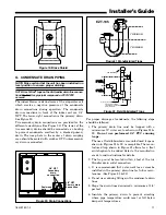
11.
Openings where field wiring enters the cabi-
net must be completely sealed.
Location of
power entry is shown on the outline drawing. Use
2.5" clear stickers to seal all unused electrical
knockouts. See Figure 13.
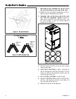
Figure 11. Remove Brackets
Remove
and
Discard
Replace
with
Narrow
Baffle
For Maximum Efficiency
on Upflow
Figure 12. Baffle Replacement
Figure 13. Electrical Knockouts
Electrical Knockout Sticker Sheet
12. After ductwork connections are made, seal air-tight
and per local codes.
13. Install FIELD CHARGER as shown in Figures 14
and 15. Ionizing pins must face downward (into the
return air stream) and electrical contacts must be
on the left side of the unit.
14. Reinstall FIELD CHARGER retainer bracket.
15. Install COLLECTION CELL as shown in Figures 14
and 15 so that electrical contacts and actuator tab
are on the left side of the unit.
16. Install filter panel with thumbscrews.