Trane 4TEE3D01B1000A Installer'S Manual Download Page 3

18-GE15D1-2

3

Installer’s Guide

16. If side, front or rear return is required, Air Handler must

be elevated or placed on a plenum [TAYPLNM100 for
4TEE3D02, 03, 04, 06, & 08 (23.5" wide), TAYPLNM101
for 4TEE3D01 (21.5" wide), TAYPLNM102 for
4TEE3D05, 07, 09, & 10 (26" wide)]. Connecting return
duct directly to the side, front or rear of the cabinet is not
approved.

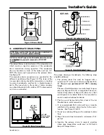
17. Route refrigerant & condensate drain lines away from Air

Handler so they do not interfere with access panels and
COLLECTION CELL removal.

18. When external accessories are used, the additional

height and width requirements must be considered in the
overall space needed.

19. These units are not approved for outdoor installation.

20. DO NOT use silicon based sealant. This causes a coating

on the FIELD CHARGER pins that will decrease the effi-
ciency of the air cleaner.

NOTE: No atomizing style humidifier is allowed in the return
plenum with the use of this unit.

21. These units are approved for draw-through application only.

22.

Flow-through Bypass Humidifiers

Excessive bypass air may cause water blow-off, which
will adversely affect system operation and air cleaner
performance. To verify bypass airflow, follow the Bypass
Humidifier Pre-Installation Checkout and Set-Up Proce-
dures available through your local distributor. Ask for
publication number 18-CH37D1-1.

Steam and Flow-through Fan Power Duct-mounted
Humidifiers. 

Follow the humidifier installation instruc-

tions. These should only be installed on the supply air
side of the system.

23. Unit installation must include either a return air duct or

grille that prevents accidental access to pins. For upflow
open air intake applications that do not have a grille or
return air duct, installation will require the use of either
BAYPLNM120, TASB215, TASB235, or TASB260 de-
pending on cabinet size.

TASB accessories can be purchased from:
Miami Tech Inc.
3611 NW 74 Street
Miami, FL 33147
Phone: 800-339-2290
Fax:: 305-693-6152
www.miamitech.com
TASB215 for use with 21.5" cabinets
TASB235 for use with 23.5: cabinets
TASB260 for use with 26.0 cabinets

24. A PRE-FILTER is not required to be installed with the

air handler containing a Whole House Air Cleaner. If the
use of a PRE-FILTER is desired, it must be installed at
least 6" away from the Whole House Air Cleaner.
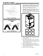
1)

3)

2)

4)

1) FIELD CHARGER

 - Charges the con-

taminants

2) COLLECTION CELL

 - removes and col-

lects very small impurities from the air.

3) Power Supply 

- the solid state power

supply converts the 24 VAC to the
high-voltage, direct current required to
power the FIELD CHARGER and COL-
LECTION CELL.

4) Safety Switch

 - cuts off all power to the

FIELD CHARGER and COLLECTION
CELL when disengaged.

Check carefully for any shipping dam-
age. This must be reported to and
claims made against the transportation
company immediately. Check to be
sure all major components are in the
unit. Any missing parts should be re-
ported to your supplier at once, and re-
placed with authorized parts only.

Figure 2. Components of the Integrated Whole House Air Cleaner

Summary of Contents for 4TEE3D01B1000A

Page 1: ...from the factory in the upflow or horizontal right configuration Variable Speed Communicating Air Handlers with Integrated Whole House Air Cleaner 4TEE3D01B1000A 4TEE3D02B1000A 4TEE3D03B1000A NOTE Rep...

Page 2: ...plate Heaters that are not factory approved could cause damage and are not covered under equipment warranty INSTALLATION LIMITATIONS RECOMMENDATIONS The general location of the Air Handler is normally...

Page 3: ...allation instruc tions These should only be installed on the supply air side of the system 23 Unit installation must include either a return air duct or grille that prevents accidental access to pins...

Page 4: ...8 LOCATED ON LEFT SIDE 1 2 3 4 Figure 4 Two Piece Wrapper Spear Closeup NOTE Make certain that the unit has been installed in a level position to ensure proper draining UPFLOW 1 Before installing unit...

Page 5: ...baffle See Figure 12 a Remove the factory installed baffle assembly from the apex of the coil by using a 5 16 nutdriver to remove the screws b Replace this baffle with the factory supplied nar row coi...

Page 6: ...ckets Remove and Discard Replace with Narrow Baffle For Maximum Efficiency on Upflow Figure 12 Baffle Replacement Figure 13 Electrical Knockouts Electrical Knockout Sticker Sheet 12 After ductwork con...

Page 7: ...Actuator Tab Electrical Contacts Electrical Contacts FIELD CHARGER COLLECTION CELL FIELD CHARGER COLLECTION CELL HORIZONTAL RIGHT Actuator Tab Electrical Contacts Electrical Contacts Figure 14 COLLECT...

Page 8: ...cal Contacts on Bottom side FIELD CHARGER COLLECTION CELL DOWNFLOW Actuator Tab Electrical Contacts Electrical Contacts FIELD CHARGER COLLECTION CELL Downflow and Horizontal Left orientations availabl...

Page 9: ...ation isolators field supplied must be placed under the unit 4 It is always recommended that an auxiliary drain pan be installed under a horizontal Air Handler See Condensate Drain Piping to prevent p...

Page 10: ...utline drawing on page 21 for sizes of the duct connections After the duct is secured seal around the supply duct to prevent air leakage NOTE If the convertible duct flanges are not used they must be...

Page 11: ...of air handler condensate drain connection Close as possible Figure 22 Field Fabricated Traps 2 MINIMUM 2 MINIMUM EZT 105 Figure 21 Manufactured Traps Figure 20 Drain Connections 3 4 NPT Primary drai...

Page 12: ...Sup port the condensate piping and traps outside the unit to prevent strain on the drain coupling H ELECTRICAL POWER WIRING 1 These Air Handlers are shipped from the factory wired for 230 Volts The u...

Page 13: ...ge 1 2 3 heat humidifier and EAC relays User Interface displays UNIT TEST EXIT Displayed for three seconds NOTE Airflow is default or programmed selections J AIRFLOW ADJUSTMENT Blower speed changes ar...

Page 14: ...14 18 GE15D1 2 Installer s Guide USERINTERFACEMENU COMMUNICATINGMODE Figure 24 User Interface Menu Communicating Mode...

Page 15: ...18 GE15D1 2 15 Installer s Guide USER INTERFACE MENU 24 VAC MODE Figure 25 User Interface Menu 24V Mode...

Page 16: ...arge Air Sensor Open Error 6 Flash N A RAS RNG ERR N A 117 Return Air Temperature Fault Return Air Temperature Range Error RAS SHORT Return Air Sensor Short Error RAS OPEN Return Air Sensor Open Error...

Page 17: ...ller s Guide M FIELD WIRING REFERENCE ONLY COMMUNICATING INDOOR UNIT WITH COMMUNICATING COMFORT CONTROL COMMUNICATING OUTDOOR UNIT COMMUNICATING INDOOR UNIT WITH COMMUNICATING COMFORT CONTROL 24 VAC S...

Page 18: ...8 18 GE15D1 2 Installer s Guide COMMUNICATING INDOOR UNIT WITH 24 VAC COMFORT CONTROL 24 VAC SINGLE STAGE COOLING COMMUNICATING INDOOR UNIT WITH 24 VAC COMFORT CONTROL 24 VAC 2 STAGE OR 2 STEP COOLING...

Page 19: ...GE15D1 2 19 Installer s Guide COMMUNICATING INDOOR UNIT WITH 24 VAC COMFORT CONTROL 24 VAC SINGLE STAGE HEAT PUMP COMMUNICATING INDOOR UNIT WITH 24 VAC COMFORT CONTROL 24 VAC 2 STAGE OR 2 STEP HEAT PU...

Page 20: ...20 18 GE15D1 2 Installer s Guide N OUTLINE DRAWING FOR 4TEE3D01 10 Printed from D802612REV03...

Page 21: ...000A 43 00 21 50 4TEE3D02A1000A 45 00 23 50 4TEE3D03A1000A 57 90 23 50 4TEE3D04A1000A 57 90 23 50 4TEE3D05A1000A 51 75 26 00 4TEE3D06A1000A 57 90 23 50 4TEE3D07A1000A 57 90 26 00 4TEE3D08A1000A 57 90...

Page 22: ...CLEANING THE COLLECTION CELL 1 Turn the air conditioning system off at the Comfort Control 2 Loosen thumbscrews to remove the filter panel Remove the COLLECTION CELL by pulling for ward See Figure 5 p...

Page 23: ...IATE GLOVES WHEN HANDLING THE FIELD CHARGER 4 Wipe down the face plate of the FIELD CHARGER with a dry shop towel or use a vacuum cleaner NOTE Do NOT disassemble the FIELD CHARGER 5 Push a block of fo...

Page 24: ...the variable speed motor d Turn the system power ON e Turn the Comfort Control to Fan only setting f Check for LED illumination on the power supply to the air cleaner LED illumination indicates High V...

Reviews: