


12
18-GE15D1-2
Installer’s Guide
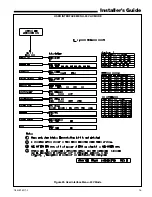
Table 1 — Control Wiring
* The maximum total cable length for the entire Comfort
Control communicating system is 500 ft. 18 AWG.
* * Maximum
total
length of low voltage wiring from outdoor
unit, to indoor unit, and to Comfort Control.
S
T
L
O
V
4
2
-
g
n
i
r
i
W
I
I
s
s
a
l
C
C
E
N
E
Z
I
S
E
R
I
W
*
*
H
T
G
N
E
L
E
R
I
W
.
X
A
M
G
W
A
8
1
T
F
0
5
1
G
W
A
6
1
.
T
F
5
2
2
G
W
A
4
1
.
T
F
0
0
3
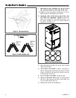
NOTE: If Air Handler is used with or without a heater,
the electrical entry hole as well as any other cabinet
penetrations must be sealed air tight.
IMPORTANT: When supplementary heaters are in-
stalled, inspect to insure that all packaging material
has been removed.
I.
CONTROL WIRING
1. Connect wiring between indoor unit, outdoor unit
and Comfort Control. The use of color-coded low-
voltage wires is recommended.
2. A low voltage terminal board is provided for control
wiring, and is located on the left side of the cross
brace in the center of the unit.
3. Field wiring diagrams on pages 18-20 show the low
voltage wiring hookup for all applicable systems.
Plug-in type electrical connectors are provided for
use with supplementary heaters.
Communicating Control Wiring
WIRE SIZE
MAX. WIRE LENGTH*
18 AWG
250 FT
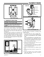
7.
Provide means for drainage to prevent winter
freeze-up of condensate line
.
8. Do not connect the drain line to a closed drain sys-
tem.
It is always recommended that an auxiliary drain pan
be installed under a horizontally installed Air Handler.
Connect the auxiliary drain line to a separate drain line
(no trap is needed in this line) and terminate according
to local codes.
NOTE: Do NOT use a torch or flame near the plastic
drain pan coupling.
NOTE: Do NOT tighten the drain pipe excessively. Sup-
port the condensate piping and traps outside the unit
to prevent strain on the drain coupling.
H. ELECTRICAL - POWER WIRING
1. These Air Handlers are shipped from the factory
wired for 230 Volts. The units may be wired for 208
Volts. Follow instructions on unit wiring diagram
located on inside blower panel housing and in the
Service Facts document included with the unit.
2. The selection of wire and fuse sizes should be made
according to the Minimum Branch Circuit Ampacity
and the Maximum Overcurrent Device listed on the
unit nameplate.
IMPORTANT: The BAYHTR** electric heat accessory,
designed for use with this air handler, may include up to a
combination of three 30 and / or 60 amp circuit breakers to
provide an electrical disconnect for service personnel that
is intended to help protect internal electrical components in
the event of a short circuit or ground fault. As designed, the
circuit breakers supplied in the BAYHTR** accessory do not
provide over-current protection of the branch circuit.
Therefore, the branch circuit(s) shall be sized and protected
according to the unit nameplate.
3. Field wiring diagrams for electric heaters and unit
accessories are shipped with the accessory.
4. Wiring must conform to National and Local codes.
Ground unit per Local codes following recognized
safety procedures.
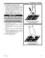
If an electric heater is not installed, the installer MUST
seal opening with a sheet metal plate made per Figure
1 and the Knockout Plate provided in the Accessory Kit
MUST be installed on the air handler and the conduit
terminated to it. The electrical connections are made
using the two power leads and ground wire connections
which are located near the discharge of the blower.
Openings where field wiring enters the cabinet
must be completely sealed.
Location of power entry
is shown on the outline drawing. Use 2.5" clear stick-
ers to seal all unused electrical knockouts. See Figure
13.