Trak-Star RailBoss Operator'S Manual Download Page 8

Positioning of Optional Hole Location Template

Template is positioned on head of rail with tapered tip fl ush 
with end of rail and side locking screws fastened to rail 
head. Notches in template give precise location of hole 
centerlines to be drilled.

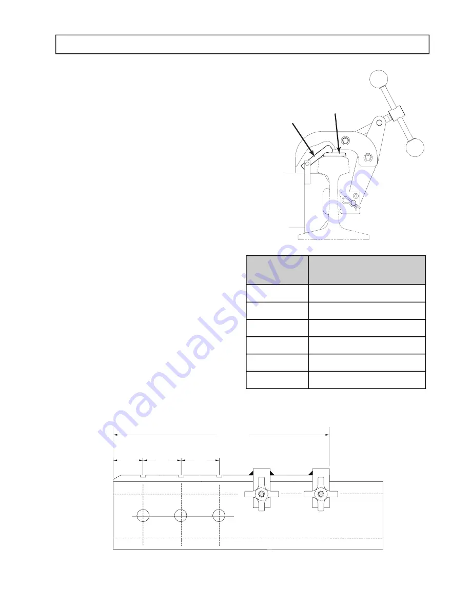
The rail clamp assembly has a locating arm which rests 
in the template notches. The locating arm is adjustable to 
accommodate the full range of rail sizes.

To use the locating arm, raise the drill unit over the rail with 
the template attached and gently rest drill down until shoes 
make contact with the rail. Flip the arm to make contact 
with the template. Slowly slide drill across the template 
until the arm falls into notch.

The arm must contact the sides of the matching notch. 
Following the Clamping  Instructions, clamp unit onto rail. 
When the hole is completed, raise the arm by fl ipping the 
arm back toward the body of the drill. Before drilling next 
hole remove chips around cutter. Then move the drill side-
ways, ensuring the arm is clear of the notch, and fl ip arm 
down. Slide the drill sideways until arm falls in the next 
notch, and repeat the procedure as necessary.

Note: The locating arm must be fl ipped back, resting 
on the body of the drill before putting the drill unit on 
the rail. Failure to do so can result in damage to the 
hole locating arm system.

Hole location templates are offered as optional equipment. 
Four of these templates are provided with established hole 
spacings. The 40570 template is produced to customer 
specifi ed hole spacing. See chart for the template to match 
your application. 

8

Template

Part No.

Hole Spacing

40570

Customer Specified

40701

3-1/2" X 6" X 6"

40702

2-11/16" X 5-1/2" X 5-1/2"

40703

2-1/2" X 5" x 5"

40704

2-1/2" X 6-1/2" X 6-1/2"

40706

2- 23/32" x 5-1/2" x 5-1/2"

Locating Arm

Location Template

28-1/2"

"A"

"B"

"C"

Specify “A”, “B”, “C” when ordering custom template

Custom Template Spacing

Summary of Contents for RailBoss

Page 1: ...OPERATOR S MANUAL PORTABLE 4 STROKE RAIL DRILL MANUAL FEED 70 LB A S C E TO 155 LB P S Serial _______________________ Date ______________...

Page 2: ...Attach the large feed handle onto the drill using the enclosed 5 32 hex wrench 7 Attach Clamp Handle using the enclosed 1 8 hex wrench 8 ADD 8 OZ OF OIL TO THE MOTOR 9 Your new Rail Drill was factory...

Page 3: ...ught in moving parts Rubber gloves and nonskid footwear are recommended when working outdoors Wear sturdy leather gloves when working indoors 14 Remove Adjusting Keys and Wrenches Form a habit of chec...

Page 4: ...erator know and understand instructions for safe operation Add engine oil to motor and use regular unleaded gasoline only Ignition switch located on engine stops motor spindle and cutter rotation See...

Page 5: ...Gold TiN Coated Part Number Black TiAlN Coated Part Number 7 8 08750 15228 15328 15 16 09375 15230 15330 1 1 0000 15232 15332 1 1 16 1 0625 15234 15334 1 1 8 1 1250 15236 15336 1 3 16 1 1875 15238 15...

Page 6: ...ricates the cutting edge helps evacuate the chips keeps the slug from expanding and helps eject the slug Various mineral and sulphur base oils are quite popular however water base solutions have bette...

Page 7: ...IL PRIOR TO STEP 2 STEP 2 RAISE REAR OF RAIL DRILL TO LOCATE SHOES IN PROPER POSITION SEE FIGURE B STEP 3 WHILE MAINTAINING CONTACT BETWEEN SHOES AND RAIL TIGHTEN CLAMP SEE FIG C STEP 4 WHEN UNIT IS F...

Page 8: ...rm by ipping the arm back toward the body of the drill Before drilling next hole remove chips around cutter Then move the drill side ways ensuring the arm is clear of the notch and ip arm down Slide t...

Page 9: ...re cutter wear and drilling problems while in the cut 14 Move feed handle to retract arbor and cutter Slug should eject from spring loaded pilot pin pressure 15 Move throttle to idle position 16 At th...

Page 10: ...very 100 operating hours 2 Clean around spark plug Remove and inspect spark plug 3 Replace spark plug if electrodes are pitted burned or porcelain is cracked Use NGK CR5HSB or equivalent 4 Check elect...

Page 11: ...ad Screw 10 24 x 3 4 Secondary Clamp Arm Lock Nut 10 24 Pin Pin Knob Set Screw 1 4 28 x 3 8 1 2 2 2 2 2 2 1 1 2 1 03522 27027 27026 04782 27025 40074 03563 27080 12 13 14 15 16 17 18 19 Clamp Turn Han...

Page 12: ...aft 82 Includes 43 46 gear shaft 83 Includes 43 2x gear shaft 84 Includes 43 2x gear shaft 85 Includes 5 12 86 Includes 57 61 87 Includes Assy 80 86 88 Includes 35 37 89 Includes 1 4 90 Includes 13 17...

Page 13: ...1 1 3 1 1 1 1 1 2 1 1 1 1 1 1 1 1 1 1 1 1 1 1 1 1 1 1 1 1 1 4 1 1 40 42 43 44 45 46 48 49 50 51 52 53 54 55 56 57 58 59 60 61 62 63 64 65 70 71 72 27016 04807 24100 27057 04804 27014 27015 27113 40558...

Page 14: ...HD5384631 NGK CR5HSB Fan Cover Cover HD5988779 Long Bolts HD5988969 Short Bolt HD5988977 Coil Assy Ignition HD5988852 Oil Alert Oil Alert Unit HD5858444 Oil Level Switch HD6005870 Under Housing Gas T...

Page 15: ...0 100 RB 1002 01910 AREA American Railway Engineering Association 100 10025 100 RE 10025 01894 110 11025 110 RE 1100 01895 112 11228 112 RE 1121 01896 115 119 11525 115 RE 1150 01897 11937 119 RE 1190...

Page 16: ...h vary from state to state To obtain warranty service return the item s transportation prepaid to your nearest Factory Authorized Repair Center or to Hougen Manufacturing Inc 3001 Hougen Drive Swartz...

Reviews: