Tractel HF 87 Operating And Maintenance Instructions Manual Download Page 16

MS 87/./. R 03/03 

16

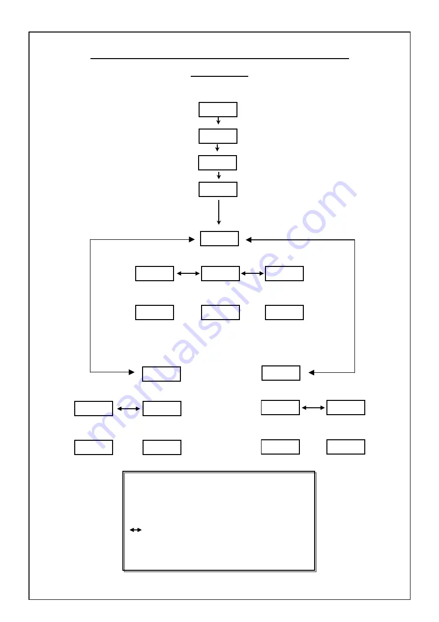
SYNOPTIC OF MANUAL TRIP POINTS ADJUSTMENT  

SET UP N°1


E + S


5   s e c


C O d E


1

1 2 3 4

S E t

. 1

Ï


Ï

C O r r

Ð


Ð

s

E

E

Ï

Ð

Ï

Ï

S - H I   S - L O

H I H I

Ð

Ð

s


E


s

E

s

E

E E

E

Ï


Ï

Ï

Ð


Ð

Ð

3 0 0 0   2 0 0 0

4 0 0 0

H Y S

C O n F  

s

E

s


E


E

Ï

Ï


Ð

Ð


Ï


Ï

S - L O

S - H I  

r E L   S P E d  

Ð

Ð

s

E

s


E


s


E


s


E


E

Ï


Ï

E E 

Ï


Ï


Ð


Ð

Ð


Ð


Ï

Ï


Ð


Ð

5 0 0

5 0 0  

H I   2 0

: Enter 

: Exit 

s


E to enter, 

S

 to exit


Ï


Move horizontally with the arrows


Ð


: Move vertically with the arrows 

Ï Ð


: Select with the arrows

.  

Ï Ð


Summary of Contents for HF 87

Page 1: ...Scoreboard displays HF 87 1 0 1 0 0 HF 87 1 IR Operating and Maintenance Instructions Equipment in accordance with CE directives MS 87 R 03 03 1 ...

Page 2: ...T UP N 2 AUTOMATIC TRIP POINTS ADJUSTMENT 17 x One safety trip point 17 x One safety trip point and slack wire rope detection 18 x One safety trip point and one intermediate trip point 19 GAIN AND ZERO ADJUSTMENT 20 SAFETY WIRING DIAGRAMS 21 22 LOAD CELL WIRING DIAGRAMS 23 x Load cell with build in converter 23 x Load cell with remote converter 24 x Sum of load cells with millivolts signal out put...

Page 3: ...e health and safety at work regulations 4 Never apply to the Dynasafe a load or an effort in excess of the working load limit and never use it for an operation for which it is not intended 5 TRACTEL SAS declines any responsibility for the consequences of dismantling or altering the machine by any unauthorised person 6 Dynasafe equipment must not be used in explosive atmospheres 7 Dynasafe equipmen...

Page 4: ...s NO 2 S HI safety trip point NO 5 Amp IN 1 tare COM common IN 2 set memory 220 220 Vca power supply IN 3 display memory Options 380 380 Vca power supply IN 4 reset memory to zero LP flashing light negative DEPHD down COM Common alarm positive DEPHM up COM Common alarm positive 0 V common for direction of operation SIR alarm negative 0 V sensor TXD data transfer 12 sensor TXD data transfer Options...

Page 5: ...socket D Connection terminals B Gain potentiometer E Scoreboard display terminals C Zero potentiometer F Label POWER SUPPLY CONNECTION When the load cell and the scoreboard display have been fitted and wired correctly switch on the power supply Once the power supply is switched on the scoreboard displays the model reference e g HF 87 1 for 2 seconds during which time the alarms are triggered and t...

Page 6: ...d to simulate the overload condition The two relays are reversed and the alarms triggered Display the parameters held in memory Press the buttons and simultaneously The scoreboard display will display the messages in sequence Display Comments 1 tESt Title of sequence 2 88880 Test of all digits 3 N Identification number of 4 0 N of the lifting device 5 S LO Intermediate trip point 6 3000 Value of t...

Page 7: ...capacity e g 20000 Lbs Crane Sheaved 4 1 CALI 20000 StEP Define the incremental steps of the display POId Calibration value regarding to a well known load SPEd2 Define the dynamic damper value DBt Double tare return to the initial zero or the preceding zero Complementary Advanced functions high accuracy calibration Available from 4 2 software version only LIN Linearity Optimisation SET L Set up fo...

Page 8: ...UL E Press E 9 425 auto The display doesn t indicate any incorrect value 10 425 E Press E a second time to confirm the zero value 11 nUL The setting of the zero point is completed Press E again and the display will now show 0 Return the display to the nuL by pressing E again 12 nUL Press the UP arrows to pass the next stage 13 SCAL auto Define the difference in signal between the zero point and th...

Page 9: ...red to a well known load 29 POId E Press E to view this parameter 30 0 auto The display show the value of the load currently suspended 31 18725 Lift an accurately known load which should represent at least 80 to 90 of the capacity of the lifting system the display indicates any incorrect value 32 18725 E Press E to correct this value 33 19975 Ø Use the arrows to correct the value in unit of measur...

Page 10: ...d DBT NO Any time you press TARE display will show 0 43 DBT E Press E to view this parameter 44 Yes or No Ø Use the arrows to select the required value Default value is YES 45 No E Press E to confirm 46 DBT Press S twice The calibration has been successfully achieved REMARK This calibration is recommended for weight estimation applications Basic calibration set the zero point corresponding to no l...

Page 11: ...set points modify not only the points values but the accuracy correction polynomial as well Generally three intermediary points are enough to increase significantly the weighing performance WARNING This part of the menu is only workable after having successfully achieved the SETUP 4 basic functions From NUL line 7 to POId line 36 Procedure x Go to Set up 4 step 47 LIN x Disable LIN parameter 47 LI...

Page 12: ...y e g 6410 Idem e g 6425 and so on x Then proceed lines 52 to 66 as follows 52 SEt L auto Accuracy optimization 53 SEt L E Press E to view this parameter 54 P 1 Ø Use the arrows to reach the point you want to set 55 P 1 E Press E to confirm your choice 56 rEad E Press E to view this parameter 57 1355 Ø Use the arrows to enter the value you previously noted as P1 58 1355 E Press E to enter the valu...

Page 13: ... 0 0 0 2 0 0 0 5 0 Y E S 0 1 9 8 5 s E Ï Ð Ï Ð Ð Ð Ð Ð Ð Ð E Ï Ð 2 0 0 0 Ï Ð Basic calibration High accuracy calibration Ï Ð P 1 S E t L s E r E A D s E s E Y E S N O s E L I n E Ï E Ï Ð Ð e t c Ï Ð Ï Ð Ï P 2 r E A D s E s E Ð E E Ï Ï Ð Ð Ï Ï r E E L s E r E E L Ð Ð s E E Ï E E E Ï Ï Ï Ð Ð Ð Ð Ï Ï 3 4 3 3 3 2 2 0 0 2 0 5 Ï Ð Ï Ð Ð Ð Enter E S Exit s E E to enter S to exit Ï Move horizontally with ...

Page 14: ... 87 R 03 03 14 Hystérésys S LO Hystérésys S LO REL HI LO S LO S HI HI HI SPED 1 40 calcul de l effet dynamique Hystérésys S HI ps 0 Charge Kg TRIP POINTS ADJUSTMENT Diagram load Tem time Load cell signal ...

Page 15: ...ccount of the dynamic effect damper Hysteresis S LO Gap value between triggering and reset of the LO relay e g S LO 5000 Kg hysteresis LO 500 Kg REL HI Triggering LO relay at 5000 Kg reset at 4500 Kg REL LO Triggering LO relay at 5000 Kg reset at 5500 Kg Hysteresis S H I Gap value between triggering and reset of the HI relay e g S HI 7000 Kg hysteresis HI 1000 Kg Triggering relay HI at 7000 Kg res...

Page 16: ... L O H I H I Ð Ð s E s E s E E E E Ï Ï Ï Ð Ð Ð 3 0 0 0 2 0 0 0 4 0 0 0 H Y S C O n F s E s E E Ï E Ï Ð Ð Ï Ï S L O S H I r E L S P E d Ð Ð s E s E s E s E E E Ï Ï E E Ï Ï Ð Ð Ð Ð Ï Ï Ð Ð 5 0 0 5 0 0 H I 2 0 Enter E S Exit s E E to enter S to exit Ï Move horizontally with the arrows Ð Move vertically with the arrows Ï Ð Select with the arrows Ï Ð ...

Page 17: ...LO S Intermediate trip point will not be used on this system setting Go to next step by pressing S As a result the relays HI and LO will trip simultaneously 9 S HI auto Safety trip point S HI see graph 10 S HI auto Lift a load equivalent to the maximum capacity of the lifting system by about 10 cm or the maximum permitted load 11 S HI E When the lad is stable confirm the trip point by pressing but...

Page 18: ...oad 10 2750 auto Display in Kg of the intermediate trip point S LO The example shows 2750 kg 11 S HI auto Using the lifting accessory which represents load N 1 lift load N 2 about 10 cm Note Up to 4 minutes is allowed to carry out this operation after which time the monitor returns to normal operation and the set up must restart at point 1 12 S HI E When the load is stable confirm the trip point b...

Page 19: ...auto Display in Kg of the intermediate trip point S LO The example shows 2750 kg 11 S HI auto Using the lifting accessory which represents load N 1 lift load N 2 about 10 cm Note Up to 4 minutes is allowed to carry out this operation after which time the monitor returns to normal operation and the set up must restart at point 1 12 S HI E When the load is stable confirm the trip point by pressing b...

Page 20: ...s x THE TEST OPERATION SHOULD HAVE BEEN SUCCESSFULLY CARRIED OUT x No load on the cell x Display in frequency mode press Ø Equipment required x A load equivalent to 100 if the working load limit of the lifting system Procedure DISPLAY ACTIONS COMMENT 1 650 Load cell out put signal in frequency e g 2 650 Set the zero With the ZERO potentiometer reduce the signal to 0 hz 2 0 3 1 4 Lift the load 5 35...

Page 21: ...C1 UP P V DOWN P V G V G V L3 L2 L1 KM17 KM15 KM16 M30 PO WE R LI MI T NO1 NO2 NO1 NO2 FU SE COM 220 380 LP COM COM SIR 0V 12 12 RCPT 0V IN1 IN2 IN3 IN4 DEPHD DEPHM TXD 0V TXD RXD RXD KM15 KM16 CONNECTION LAYOUT 1 SAFETY TRIP POINT 1 SLACK WIRE ROPE POINT ...

Page 22: ...1 UP P V DOWN P V G V G V L3 L2 L1 KM17 KM15 KM16 M30 PO WE R LI MI T NO1 NO2 NO1 NO2 FU SE COM 220 380 LP COM COM SIR 0V 12 12 RCPT 0V IN1 IN2 IN3 IN4 DEPHD DEPHM TXD 0V TXD RXD RXD KM15 KM16 CONNECTION LAYOUT 1 SAFETY TRIP POINT 1 INTERMEDIATE TRIP POINT ...

Page 23: ... BORNIER DE RACCORDEMENT A PRISE DIAGNOSTIC B POTENTIOMETRE DE GAIN C POTENTIOMETRE DE ZERO WIRING DIAGRAMS Remarks x Use shielded 4 x 0 34 mm wires to connect the load cell x Shield must be connected only on the display side Load cell with build in converter UTOCOLLANT SUR LE BOUCHON Sticker on the cover back A Diagnostic plug B Gain Span potentiometer C Zero potentiometer D Terminal ...

Page 24: ... SIDE ZERO GAIN IR 10 100 POWERDYN Conditionneur HF84 1 HF87 HF84 1 A A I I HF84 1 0V 12 12 RCPT A A I I BL 0 S A MP 26096 0 S Load cell with remote converter Converter Capteur Load cell Tresse Shield Shield must be connected to the HF 84 1 side on the BL terminal ...

Page 25: ...HF84 2 0V 12 12 RCPT HF87 HF84 2 HF84 2 POWER LIMIT A I I BL COMP SIDE ZERO GAIN 0 S A MP 26096 0 S A A I I BL A A I I BL Several load cells with sum function in millivolts Conditionneur Sommateur HF84 2 Converter sum unit HF 84 2 Capteur 1 Load cell Capteur 2 Load cell Tresse Shield Tresse Shield Shield must be connected to the HF 84 1 side on the BL terminal ...

Page 26: ...OWER LIMIT GAIN ZERO POWER LIMIT HF87 bornier 5 bornier 1 bornier 2 0 S 0 S HF83 2 bornier 5 IR 10 100 POWERDYN 0 S Tresse 0 0 0 MMATEUR HF83 Several load cells with sum function in frequency SO CAPTEUR2 HF83 2 Load cell 2 HF83 2 CAPTEUR1 Load cell CAPTEUR 2 Load cell 2 CAPTEUR 1 Load cell 1 ...

Page 27: ...MS 87 R 03 03 27 IR 10 100 POWERDYN HF89 2 1 2 4 0V 12 RCPT HF87 HF89 2 Radio receiver Wiring ...

Page 28: ...destruction of some electronic components To check frequency signal press Ø 1 Increase the frequency up to 500 hz with the zero potentiometer page 20 2 Double check wiring Double check power supply Contact Tractel ASS Contact Tractel ASS Er 21 Frequency out put signal could not be read by the display Signal greater than 9999 Hz Load cell is over stressed Display fault Load cell fault NOTE Wrong po...

Page 29: ... reset the zero point SEt 4 Set up N 4 Display calibration menu COdE Access Code COrr Correction COnF Configuration HYS Hysteresis rEL Relay SPEd Calculation of the dynamic effect N Crane identification n 3 10 Program version End End of procedure nUL To fix the zero point SCAL Frequency range between Zero NUL and nominal capacity CALI CALI Nominal capacity StEP Increment POId Well known load 87 1 ...

Page 30: ...NOTES MS 87 R 03 03 30 ...

Reviews: