


4.1
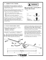
ASSEMBLY OF THE 4’ SKYBEAM
®
The SKYBEAM must be pre-assembled in accordance with
these instructions. The counterweights are assembled on the
counterweight Frame and all roof loads must be confirmed in
accordance with this manual.
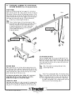
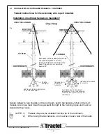
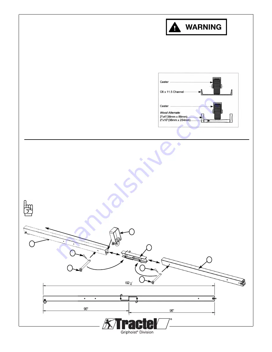
When using casters, install guide channels on structure to guide
the casters. Two channels are required, one for the front
support and one for the rear counterweight Frame. See Fig. 1.
• Block the end of guide channels with end stops.
• Always use a guide channel on roofs to distribute bearing
load.
• Guide channels to run parallel to building face.
• Rigidly secure both ends of guide channels to the structure
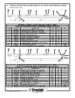
Determine if you are using the two or three beam version of the
4’ Skybeam. Both have a 4’ reach and a 1,000lb (454 kg)
capacity, the advantage of the three piece beam is less
counterweights are required (16) versus (28) required for the
two beam variation.
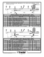
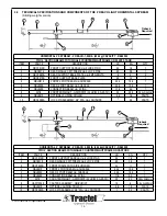
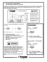
4.2 TWO PIECE SKYBEAM ASSEMBLY. (MRB2P)
Ensure you have the correct components for assembly
1 – MRBL0200 Connection Beam (1)
1 – MRBL0210 4’ Front Beam (2)
1 – MRBL0230 4’ Rear Beam (3)
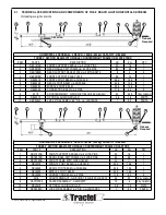
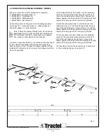
Lie the components on the ground in the following sequence:
Front beam (2) – Connection Beam (1) – Rear Beam (3)
Note: If Using the Optional Sliding Collar (for Horizontal
applications only) (4), slide the collar onto the bottom of
the Front Beam (2) before connecting the unit together.
Then slide the collar behind the front shackle.
© 2012 Tractel Ltd. All Rights Reserved.
12
Fig. 1
3
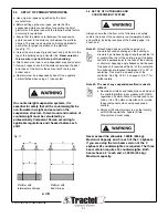
When using casters, channel guides or
roofjacks must be used.
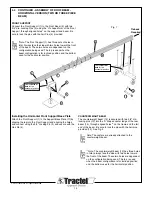
1) Slide the connection beam (1) into the back of the front
beam (2) to so the first hole aligns with the back hole of
the front beam as shown in Fig 2. Connect the beams
together with the provided 3/4" locking pin (5) and secure
the locking pin with the hair pin (6) provided.
2) The rear beam (3) is then slide over the remaining
section of the connection beam and joined at the front
hole of the rear beam as shown Fig. 2. Connect the
beams together with the provided 3/4" locking pin (5) and
secure the locking pin with the hair pin (6) provided.
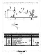
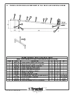
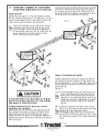
For Assembly in the horizontal position go to section 4.4,
for the inclined position go to section 4.5.
1
2
5
5
6
6
4
Fig. 2
Fig. 3


