


4.4
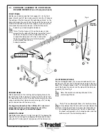
CONTINUED - ASSEMBLY OF 4’ ROOF BEAM -
INCLINED VERSION (Two or three piece beam)
FRONT FRAME
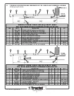
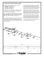
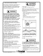
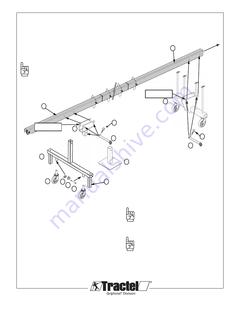
Set the reach and connect the front support (1) to the front
beam (2) with two 3/4" dia. locking pins (3) onto the ‘U’ shaped
Top Ledger of the front support, through aligned holes* on the
frame and beam. Be sure to lock the pins with the hair pins (4)
provided. When attaching the front support (1) ensure you do
not exceed the maximum extension of the front beam (2)
based on your load weight calculations.
*Note: The front support (1) has three holes in total,
always face the side with two holes toward the front of
the beam. These two holes are dependent on the
configuration being used. The top is used when
the beam configuration is for inclined position
and the bottom used for the
horizontal position.
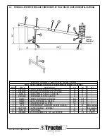
INCLINED BEAM
Attach casters (5) to the front leg (6) by aligning holes in the
leg with those of the casters and connect with the 0.375" bolt
(7), washer (8) and nut (9). Then slip the front leg into the front
support and align the holes and connect using a 3/4” locking
pin (3) and secure with the hair pin (4).
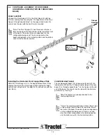
For bigger loads/reaches than 1000lbs. /5 Ft. use wood
plates under the two vertical extensions (10) of the
inclined front support, to unload the wheels.
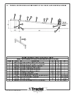
HORIZONTAL BEAM
Attach the front support (1) to the front leg (11) by slipping the
Leg into the front support and aligning the holes and connect
using the 3/4” locking pin (3) and secure with the hair pin (4).
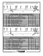
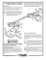
COUNTERWEIGHT BEAM
The counterweight beam (12) is secured with two 3/4" dia.
locking pins (13) into the ‘U’ shaped center ledge of the rear
beam (14), through aligned holes** on the frame and the tail
end of the beam. Be sure to lock the pins with the hair pins
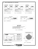
provided (15). See Fig. 5
Note: The casters are already attached to the
counterweight beam.
**Note: The counterweight beam (12) has three holes
in total, always face the side with two holes toward the
front of the beam.These two holes are dependent on
the configuration being used. The top is used when
the beam configuration is for inclined position and the
bottom used for the horizontal position.
© 2012 Tractel Ltd. All Rights Reserved.
14
6
2
8
5
1
7
14
12
3
9
Fig. 6
Tieback
Required
11
4
10
13
15
Use the
top hole
for
the reclined position
Use the
top hole
for
the reclined position