background image

20 


3.3.6 Skew Angle Setting (note the skew angle should be set as a minus number) 

The TS-series antenna’s skew module works fully automatically. However, if you wants to 

change  the  skew  angle  for  any  reason,  you  may  use  the  ‘Manual  Mode’.  You  may  also 

optimize the skew angle by using trim function when desired satellite has polarity offset.   


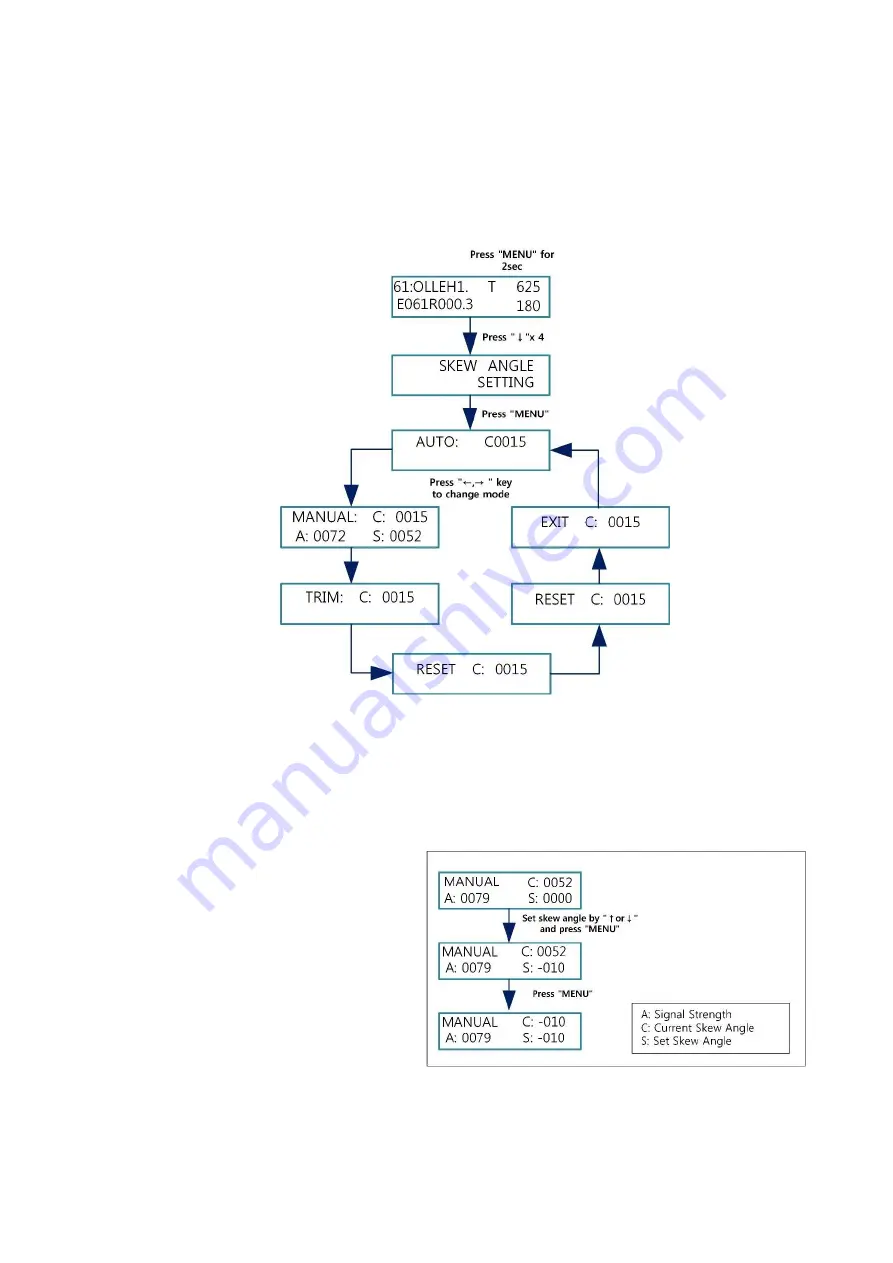
Figure 31 – Skew Angle Menu   


a. Auto Mode   

In the Auto mode, the ACU displays the skew angle calculated by the PCU. The 

TS series default skew mode is auto. The TrackSAT automatically changes the skew 

angle when the targeting satellite is changed. 

b. Manual Mode   

You  can  change  the  skew 

angle  to  the  desired  skew 

angle manually. (see Figure- 

32) 

NOTE

:  ‘C:’  refers  to  the 

current  skew  angle.  ‘A:’ 

refers to signal strength. ‘S:’ 

refers to the user setting the 

skew angle. 

Figure 32 – Manual Skew Agle Setting Step


Summary of Contents for UltraTrack TS61

Page 1: ...TrackSAT UltraTrack TS61 Installation and Operation User Manual Ku BAND TVRO ANTENNA with Australian 10700 LNB Revision Ver 1 20 ...

Page 2: ...tion about TrackSAT UltraTrack TS series equipment installation operating procedures performance and suggestions for its servicing and care TrackSAT recommends you to read this operation manual from cover to cover and refer to it frequently Our Australia dealer organization and customer service department stands ready to serve you The following service are offered by TrackSAT dealers The warranty ...

Page 3: ...tion 8 2 7 2 Multi IRD Configuration 9 2 8 Connecting the Ship Gyro 10 3 Operation 12 3 1 ACU Front Panel Layout 12 3 1 1 ACU Main Display 12 3 1 2 LED Indicator 13 3 1 3 Keypad Function 13 3 2 Normal Mode 14 3 2 1 Changing Satellite 14 3 2 2 Antenna Status Monitoring 15 3 2 3 M C Connecting PC 15 3 2 4 Satellite Researching 15 3 2 5 Checking the System Error 15 3 2 6 Checking System Communication...

Page 4: ... 3 6 c Trim 22 3 3 6 d Reset 23 3 3 6 e Save 23 3 3 6 f Exit 23 3 3 7 Satellite Name Edit 23 3 3 8 Save and Exit 24 Appendix A Satellite Library 25 Appendix B Specifications 28 Appendix C UltraTrack S C S Software 29 Appendix D Error Code 30 Appendix E FAQs 31 Appendix F Radome Dimension Mounting Hole Layout 32 ...

Page 5: ...tures Attitude Heading Reference system AHRS using an IMU sensor 3 axis gyro scope 2 axis acceleration High performance stabilization in rough weathers Honest 3 axis system Stabilized azimuth and elevation with a skew unit Stabilized skew system guarantees perfect searching and tracking Automatic skew control Antenna control unit displays heading value without gyro connection using AHRS derived fr...

Page 6: ...em and RF equipment RF Unit receives optimum satellite signal from the satellite Radome ultra efficient plastic radome provides minimal loss and protect from marine environment BDU Below Deck Unit The BDU controls the stabilized antenna and consists of the UltraTrack TS series interface ACU 2 1 1 Installation Kit List Figure 3 Customer Kit List Figure 1 Radome Figure 2 KA78 ACU ...

Page 7: ...e boat s motion or vibration Environmental must operate in controlled environment temp altitude dust vibration corrosive explosive free EMC elective magnetic compatibility to ensure the antenna system provides the highest protection against interfering The antenna should be in front of a radar beam Cable must be shielded and all equipment must be covered During the lifting the system has to be bal...

Page 8: ... the power before removing the securing materials It may cause the damage to the system When the antenna needs to be relocated the securing material must be re installed to prevent damage from free moving while in transit 2 4 Selecting Installation Site The following should be kept in mind when selecting a physical location on the vessel for the antenna equipment 2 4 1 ADU Above deck Unit antenna ...

Page 9: ...t will arrive with the TrackSAT control software pre installed and will automatically run on the power up and also operation is largely automatic but it is desirable that it be monitored periodically Therefore it is beneficial that it be sited in a location with easy operator access ACU should be installed in a radio room where In a cool and dry location In a place that not susceptible to magnetic...

Page 10: ...ing the Antenna Lift the system onto its supporting post and position the antenna base plate in place in position over the mounting holes and cable access Ensure the radome is pointing correct direction align the BOW label on the bottom plate with the ship s bow and is parallel to the vessel s center line see Figure 10 Insert the flat and spring washer and a mounting bolt to each mounting holes ar...

Page 11: ...les from BDU to ADU The antenna cable must be connected to the ACU Antenna Control Unit and the antenna unit Follow the steps below Determine the type of cable to be used depends on the cable length required see Table 1 Bring the RF cables with F male type connector from BDU Below Deck Unit up through the cable access hole Lay the cables through the waterproof fittings and close with sealing mater...

Page 12: ...n installing the cables Make sure cables are not excessively bent kinked and twisted Unused coax connections on the connector bracket must be terminated with a 75 ohm terminator 2 7 ACU Installation The KA 78 ACU is connected with various systems such as a Satellite receiver ship s gyro PC etc There are several functional connections that may be made on the various connectors To starts place the A...

Page 13: ...ti IRD Configuration This configuration can be used with or without a multi switch But a multi switch may need to be used if you have multiple Foxtel or VAST set top boxes An additional RF cable connection required for multiple IRD s Connect the DC power adapter cable to the power connector from the power source 100 240 V AC Connect the RF cable threaded from the RF4 port on the ADU to the Antenna...

Page 14: ... you will need to purchase a suitable DB 9 female type connector see Figure 15 Strip back the insulation of each cable and connect a cable to each terminal of the DB 9 connector Tighten the locking screws of the DB 9 connector Connect DB 9 connector to the NMEA port on the ACU When NMEA signal is accepted via NMEA System will be automatically restarted No additional setting required Figure 16 NMEA...

Page 15: ...m the user must understand and use functions in the ACU operation mode 3 1 ACU Front Panel Layout Figure 18 ACU Front Panel 3 1 1 ACU Main Display The KA 78 ACU shows essential data to allow the user determines the antenna system performance see Figure 19 Figure 19 Main Display ...

Page 16: ...ction The following table provides a quick reference source on Key Mapping of the ACU MENU 1 press button for checking error code 2 press button for 2 sec to enter the set up mode 3 used as an Enter key TRACK 1 press button for checking the antenna status data use button to scroll down 2 press button for 2 sec for checking PCU ACU version 3 used as a left arrow key M C 1 press button for connectin...

Page 17: ...ck the satellite ID signal strength in AGC and C N level searching reference tracking reference DVB carrier lock status On No tracking status On No searching mode Auto default antenna status initializing searching tracking the NID Network Identification Number signal and satellite longitude To use this function press TRACK button and use key to scroll up down see Figure 23 In addition NID signal w...

Page 18: ...e 3 2 6 Checking System Communication Status User may check communication status between ACU and PCU Figure 25 Checking Communication Status In the Figure 25 Packet is the number of command from ACU and Loss is the number of loss on the PCU More loss means having more system communication error 3 3 Set up Mode To enter the set up mode press MENU button for 2 sec and use key to change menu and pres...

Page 19: ...t allows users to access the antenna via PC to change antenna parameters and configuration NOTE TrackSAT provides the remote access PC software SCS for the antenna monitoring and setting on your PC see Appendix C software download 3 3 2 Setting GPS Information In the event of invalid GPS data or GPS malfunction You may input your current latitude and longitude information See figure 27 NOTE This d...

Page 20: ...om among the DiSEqC OFF or the DiSEqC 1 2 ON or 22KHz tones or Direct TV before selecting the satellites Selecting Off is the correct setting for one VAST box or Foxtel box non IQ model 250 and for one of each set 22KHz Satellite 69 is for VAST Satellite 70 is for Foxtel With a Foxtel IQ box you will need to set the 22KHz tone function after setting Satellite 69 70 RF4 should go to the ACU then Fo...

Page 21: ...e using the Next button from Sat A to Sat E in programed order After selecting the satellites from A to E the KA 78 ACU changes the satellite when the user presses the Next button DiSEqC LED indicator status on the ACU is OFF Figure 29 DiSEqC OFF Setting DiSEqC Mode LED Status OFF OFF 22KHz Tone Blink DiSEqC 1 2 ON DirecTV Blink rapidly Table 3 DiSEqC LED Status ...

Page 22: ...EqC LED indicator status on the ACU is blinking c DiSEqC 1 2 Mode By this function the antenna automatically switches between 4 satellites in programed order when the antenna receives DiSEqC signal from the satellite TV receiver Select DiSEqC 1 2 mode in the Program Satellite menu Select satellites select your desired 4 satellites for SAT A B C and D Select one any satellite for remaining slot SAT...

Page 23: ...19 Figure 30 Satellite Parameter Edit ...

Page 24: ...llite has polarity offset Figure 31 Skew Angle Menu a Auto Mode In the Auto mode the ACU displays the skew angle calculated by the PCU The TS series default skew mode is auto The TrackSAT automatically changes the skew angle when the targeting satellite is changed b Manual Mode You can change the skew angle to the desired skew angle manually see Figure 32 NOTE C refers to the current skew angle A ...

Page 25: ...n equator is not used as a reference for various reasons Thus there might be the polarity offset between calculated skew angle by PCU and true skew angle on the satellite that polarity You may check whether there is polarity offset or not on your satellite If there is skew angle should be changed to get a higher signal note set skew to a number i e 41 Figure 33 Skew Trimming Step NOTE the skew tri...

Page 26: ...ay edit the name of preset 5 satellites Sat A E see Figure 33 Figure 34 Satellite Name Edit 3 3 8 Save and Exit Save your changes before leave the set up menu Otherwise the previous parameters will be restored ...

Page 27: ... 000 000 Conus 10 072 0W AMC 6 HL DVBS1 11 652 000 2 163 000 11 101 0W DirecTV 8 R RL DSS 12 516 000 20 000 000 12 101 0W DirecTV 4S L LL DSS 12 530 000 20 000 000 13 119 0W DirecTV 7S R RL DSS 12 603 000 20 000 000 14 119 0W DirecTV 7S L LL DSS 12 588 000 20 000 000 15 101 0W User 5 RL DVBS1 12 224 000 20 000 000 16 101 0W User 6 RL DVBS1 12 224 000 20 000 000 17 101 0W User 7 RL DVBS1 12 224 000...

Page 28: ...0W User 15 HH DVBS1 11 960 000 30 000 000 39 095 0W User 16 HH DVBS1 11 960 000 30 000 000 40 095 0W User 17 HH DVBS1 11 960 000 30 000 000 3 Europe Sat ID Satellite Longitude Satellite Name Polarity LO Band Searching Standard Frequency KHz Symbol Rate KHz Beam 41 019 2E Astra1L HH DVBS1 12 633 000 22 000 000 1L 42 028 2E Eurobird1 HH DVBS1 12 560 000 27 500 000 Fixed 43 028 2E Astra2B HH DVBS1 12...

Page 29: ...CSAT3A HH DVBS2 12 328 000 23 303 000 Ku 65 124 0E JCSAT4A HH DVBS2 12 283 000 23 303 000 Japan 66 166 0E Intelsat8 HH DVBS1 12 726 000 28 066 000 Austra lia 67 144 0E Superbird C2 HH DVBS1 12 523 000 21 096 000 Japan 68 95 0E NSS6 HH DVBS1 12 647 000 27 500 000 India 69 156 0E Optus D3 VH AUTO 12 177 000 27 800 000 VAST 70 156 0E Optus D3 HH AUTO 12 177 000 27 800 000 FOXT 71 152 0E Optus D2 HH D...

Page 30: ...otion Roll Pitch 25 Tracking Speed More than 50 sec Platform 3 axis Elevation Angle 7 to 85 GPS Yes Vibration Damper N A DiSEqC DiSEqC 1 2 22 KHz DirecTV Temperature 25 C to 55 C Humidity Up to 100 40 C Below Deck ACU Size 232 W 85 D 34 H mm External I O RS422 Mini USB Input Power 110 220 VAC Gyro Compass Input NMEA Packing Size 82 x 82 x 92cm Gross weight 27kg Packed by Paper carton Specification...

Page 31: ... at www TrackSAT com au Before starts you need to find out what version of S C S should be used for your antenna system and download correct version of the PC software Download and install both SCS and USB Driver software 1 Software Download Visit www TrackSAT com au Select download area Click on TS series download SCS 1 8 3 file to download Click on TS series download CP210x_VCP for KA78 file to ...

Page 32: ...nge 0X 00 08 00 00 Roll gyro scope not in valid range 0X 00 10 00 00 Pitch gyro scope not in valid range 0X 00 20 00 00 yaw gyro scope not in valid range 0X 00 40 00 00 Ship Rotate over 50degree during initialization 0X 00 00 01 00 Elevation Min Limit Switch error during initialize 0X 00 00 02 00 Skew Max Limit Switch error during initialize 0X 00 00 03 00 Skew Min Limit Switch error during initia...

Page 33: ...the satellite coverage footprint signal power levels are much weaker than the center of the footprint and your receiver can t obtain the programming 3 How to connect Multiple TV to one TS61 antenna It is possible to enjoy different TV channels on multiple TV screens with one TS series antenna Each TV requires to have its own IRD satellite receiver and maybe a multi switch not supplied need to be c...

Page 34: ...30 APPENDIX F Radome Dimension and Mounting Hole Layout ...

Page 35: ...rackSAT 2015 Warranty Policy does not cover any television monitors satellite receivers modems cables computers gyros and any other accessories below deck or above deck Defects failures and or damages due power failures surges fires floods snow ice lightning excessive heat and cold accidents unauthorized tampering will void this warranty policy The warranty policy is voidable in the event a distri...

Page 36: ...ary to TrackSAT TV Pty Ltd This document may not be reproduced or distributed in any form without the consent of TrackSAT TV Pty Ltd The information in this document is subject to change without notice Revision Date Description Prepared by Approved by Remarks 1 2 Feb 2015 Initial Release PCU Ver K1 050 ACU Ver 1 20 Ted C Creed ...

Reviews: