Printed in the Federal Republic of Germany
TR-Electronic GmbH 2019, All Rights Reserved
06/12/2019
TR - ECE - BA - GB - 0142 - 01
Page 21 of 29
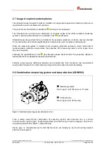
Figure 1: Installing the flange, illustration showing the principle
Components:
1: Measuring system
2: Parallel key
3: Centering collar
4: Machine
5: Coupling with groove
6: Drive shaft


