background image


User's Manual  l  TQMLS10xxA UM 0105  l  © 2022, TQ-Systems GmbH 


Page  17 


4.13


I

2

C bus 

The I

2

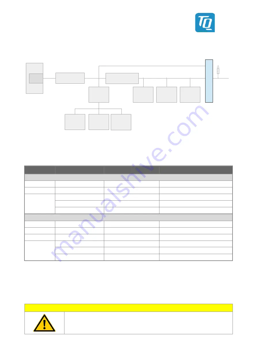
C devices on the TQMLS10xxA are connected to the I2C1 bus. 


LS10xxA 

RTC

CPLD

EEPROM

Board

Controller

Temp. Sensor

+

EEPROM

IIC1

Optional 
external 
Pull-Ups 
required

External 
Devices

DVDD ↔ 

3.3 V (LDO)

Level Shifter

3.3 V (LDO) 

↔ VCC

3V3

IIC1_MOD

I2C_BRD

L-ASC10

Level Shifter

24LC256T

PCF95063

SE97BTP

Temp. Sensor

+

EEPROM

SE97BTP

I2C3_MCU

IIC1


Figure 16:  Block diagram I

2

C bus 1 structure on TQMLS10xxA 

 
4.7 k

 Pull-Ups at the I

2

C bus are assembled on the TQMLS10xxA. More devices can be connected to the bus but then additional 

external Pull-Ups may be required on account of the higher capacitive load. 
 

Table 7: 

I

2

C addresses 

Device 

Function 

7-bit address 

Remark 

Connected to Board Controller, not accessible 

L-ASC10 

Voltage Monitoring 

0x60 / 110 0000b 

– 

MachX03 

CPLD 

(n.a.) 

– 

SE97B 

Temperature sensor 

0x1B / 001 1011b 

Access to temperature registers 

EEPROM 

0x53 / 101 0011b 

R/W access in Normal Mode 

EEPROM 

0x33 / 011 0011b 

R/W access in Protected Mode 

Connected to LS10xxA, accessible 

24LC256 

EEPROM 

0x57 / 101 0111b 

– 

STM32 

Board Controller 

0x11 / 001 0001b 

Should not be altered 

PCF85063A 

RTC 

0x51 / 101 0001b 

– 

SE97B 

Temperature sensor 

0x18 / 001 1000b 

Access to temperature registers 

EEPROM 

0x50 / 101 0000b 

R/W access in Normal Mode 

EEPROM 

0x30 / 011 0000b 

R/W access in Protected Mode 


4.14


TQMLS10xxA interfaces 

4.14.1


Pin multiplexing 

When using the processor signals the multiple pin configurations by different processor-internal function units must be taken 

note of. The pin assignment listed in Table 8 to Table 11 refer to the corresponding standard BSPs of TQ-Systems GmbH  

in combination with the Starterkit MBLS10xxA. For standard BSPs, see 1.9. 
 

Attention: Destruction or malfunction 


Depending on the configuration many CPU pins can provide several different functions. 
Please take note of the information concerning the configuration of these pins in (1), before 

integration or start-up of your carrier board / Starterkit. 


Summary of Contents for STKLS10 A Series

Page 1: ...TQMLS10xxA User s Manual TQMLS10xxA UM 0105 21 03 2022...

Page 2: ...r up sequencing 11 4 7 4 Voltage monitoring 11 4 7 5 Power consumption 12 4 8 Reset structure 13 4 9 Memory 14 4 9 1 DDR4 SDRAM 14 4 9 2 SPI NOR flash 14 4 9 3 EEPROM 24LC256 14 4 9 4 eMMC 14 4 10 Tem...

Page 3: ...0105 l 2022 TQ Systems GmbH Page ii 8 ENVIRONMENT PROTECTION 28 8 1 RoHS 28 8 2 WEEE 28 8 3 REACH 28 8 4 EuP 28 8 5 Battery 28 8 6 Packaging 28 8 7 Other entries 28 9 APPENDIX 29 9 1 Acronyms and def...

Page 4: ...Block diagram LS1088A Octal Cortex A53 7 Figure 5 Block diagram RCW source selection 9 Figure 6 Block diagram JTAG interface 10 Figure 7 Wiring of JTAG_TRST and PORESET 10 Figure 8 Wiring of JTAG chai...

Page 5: ...ected Values added Reworked Figure 9 added Information added Chapter added Footnotes added Updated Link to LS1043A Errata added 0102 29 11 2019 Petz All Table 5 4 14 2 Links updated Clarified Chapters...

Page 6: ...demarks are rightly protected by a third party 1 3 Disclaimer TQ Systems GmbH does not guarantee that the information in this User s Manual is up to date correct complete or of good quality Nor does T...

Page 7: ...d This symbol represents important details or aspects for working with TQ products Command A font with fixed width is used to denote commands contents file names or menu items 1 7 Handling and ESD tip...

Page 8: ...rer s specifications of the components used for example CompactFlash cards are to be taken note of They contain if applicable additional information that must be taken note of for safe and reliable op...

Page 9: ...or Cortex A72 cores Quad Cortex A53 or Cortex A72 cores or octal Cortex A53 cores with QorIQ technology The TQMLS10xxA extends the TQ Systems GmbH product range and offers an outstanding computing per...

Page 10: ...xA provides the following key functions and characteristics Layerscape CPUs LS1043A LS1023A LS1046A LS1026A LS1088A Oscillators Reset structure Power supply and power sequencing Voltage supervision Ho...

Page 11: ...NICS 4 1 LS10xxA 4 1 1 LS10xxA variants block diagrams The LS10xxA module family is available with three variants of the LS10xxA CPUs from NXP The following block diagrams illustrate the differences b...

Page 12: ...User s Manual l TQMLS10xxA UM 0105 l 2022 TQ Systems GmbH Page 7 Figure 3 Block diagram LS1046A Quad Cortex A72 Source NXP Figure 4 Block diagram LS1088A Octal Cortex A53 Source NXP...

Page 13: ...es at up to 10 GHz 8 lanes at up to 10 GHz PCI Express controllers 3 Gen 2 0 controllers 5 Gbit s Root complex supported 4 2 and 1 link widths 3 Gen 3 0 controllers 8 Gbit s Root complex or end point...

Page 14: ...ource is selected with signals BOOT_CFG 1 0 Table 3 RCW source selection BOOT_CFG1 BOOT_CFG0 RCW Source Low Low QSPI NOR Flash Low High I2 C LS1088A only High Low SDHC High High eMMC BOOT_CFG 1 0 is i...

Page 15: ...tors TRST is pulled at the same time as PORESET but can also be pulled Low using an external debugger while PORESET remains unchanged Figure 7 Wiring of JTAG_TRST and PORESET The CPLD is also in the J...

Page 16: ...eedback voltages The TQMLS10xxA provides the respective voltages in order to enable a simple connection according to customer requirements on the carrier board The voltages generated on the TQMLS10xxA...

Page 17: ...12 76 W 85 C U Boot memory test 6 72 W 14 2 W 15 72 W Linux 100 CPU load 8 05 W 1 15 6 W 2 18 9 W 3 Attention Destruction or malfunction TQMLS10xxA heat dissipation The TQMLS10xxA belongs to a perfor...

Page 18: ...ectors CPLD Reset Monitor RESIN LS10xxA PORESET PORESET Board Controller RESET_OUT V26 CPLD Voltage Monitoring PGOOD SYSC_POR RESET_REQ Open Drain RESET_REQ_OUT JTAG_TRST DDR4 DDR4_RST_EN TQMLS10xxA c...

Page 19: ...ccess is permitted Write protection is controlled by the CPLD Write_Protect of the EEPROM is not connected directly to the TQMLS10xxA connectors but can be controlled indirectly via USR_GPIO_1 EEPROM...

Page 20: ...warning at a programmed trigger level During power up the sensor is configured to T_CRIT_LOKAL 95 C by the Board Controller This value can be overwritten by the boot loader the operating system or the...

Page 21: ...ontroller LS CPU RTC I C Bus 32 kHz Level Shifter 3 3 V 1 8 V RTC_INT _OUT CPU_RTC CLKOUT INT Figure 14 Block diagram RTC interface The RTC has I2 C address 0x51 101 0001b The RTC is clocked with a 32...

Page 22: ...s to temperature registers EEPROM 0x53 101 0011b R W access in Normal Mode EEPROM 0x33 011 0011b R W access in Protected Mode Connected to LS10xxA accessible 24LC256 EEPROM 0x57 101 0111b STM32 Board...

Page 23: ...VDD 59 60 DGND Ground 0 V 0 V Ground DGND 61 62 USR_GPIO_6 SYSTEM 1 8 2 5 3 3 V 4 I I 1 8 2 5 3 3 V 4 SYSTEM USR_GPIO_7 63 64 DGND Ground 0 V 3 3 V Factory Test I2C_BRD_SDA 65 66 BCTL_UARTx_TX Factory...

Page 24: ...B3_RX_P USB I A3 0 V Ground DGND 63 64 USB3_RX_M USB I A4 M4 I O 1 8 3 3 V 8 USB USB2_PWRFAULT 65 66 DGND Ground 0 V 0 V Ground DGND 67 68 DGND Ground 0 V P3 I O 1 8 3 3 V 9 SDHC SDHC_CLK_MOD 69 70 US...

Page 25: ...EC1_RXD3 23 24 DGND Ground 0 V 0 V Ground DGND 25 26 SWDIO Factory Test 3 3 V I O I 1 8 3 3 V 12 SYSTEM SDHC_EXT_SEL 27 28 SWCLK Factory Test 3 3 V I O O 3 3 V SYSTEM RTC_INT_OUT 29 30 DGND Ground 0...

Page 26: ...6 SD1_TX3_P SERDES 1 35 V 18 O AD11 AH11 I 0 9 1 0 V 19 SERDES SD1_RX3_N 57 58 DGND Ground 0 V AG11 I 0 9 1 0 V 19 SERDES SD1_RX3_P 59 60 DGND Ground 0 V 0 V Ground DGND 61 62 SD2_TX0_N SERDES 1 35 V...

Page 27: ...7 TQMLS10xxA assembly top Figure 18 TQMLS10xxA assembly bottom The labels on the TQMLS10xxA show the following information Table 12 Labels on TQMLS10xxA Label Text AK1 Serial number AK2 First MAC addr...

Page 28: ...xxA UM 0105 l 2022 TQ Systems GmbH Page 23 5 MECHANICS 5 1 Dimensions TQMLS1043A Figure 19 TQMLS1043A dimensions side view Figure 20 TQMLS1043A dimensions top view Figure 21 TQMLS1043A dimensions top...

Page 29: ...Systems GmbH Page 24 5 2 Dimensions TQMLS1046A TQMLS1088A Figure 22 TQMLS1046A TQMLS1088A dimensions side view Figure 23 TQMLS1046A TQMLS1088A dimensions top view Figure 24 TQMLS1046A TQMLS1088A dimen...

Page 30: ...ors as well as the carrier board connectors while removing the TQMLS10xxA the use of the extraction tool MOZI52XX is strongly recommended See chapter 5 8 for further information Note Component placeme...

Page 31: ...rticularly the tolerance chain PCB thickness board warpage BGA balls BGA package thermal pad heatsink as well as the maximum pressure on the LS10xxA must be taken into consideration when connecting th...

Page 32: ...e measures always have to be implemented on the carrier board no special preventive measures were planned on the TQMLS10xxA The following measures are recommended for a carrier board Generally applica...

Page 33: ...n the TQMLS10xxA 8 6 Packaging By environmentally friendly processes production equipment and products we contribute to the protection of our environment To be able to reuse the TQMLS10xxA it is produ...

Page 34: ...ectromagnetic Compatibility eMMC embedded Multi Media Card ESD Electrostatic Discharge eSDHC enhanced Secure Digital High Capacity EU European Union EuP Energy using Products FC PBGA Flip Chip Plastic...

Page 35: ...REACH Registration Evaluation Authorisation and restriction of Chemicals RF Radio Frequency RGMII Reduced Gigabit Media Independent Interface RoHS Restriction of the use of certain Hazardous Substance...

Page 36: ...uments No Name Rev Date Company 1 Reference Manuals LS1043A LS1046A LS1088A Rev 3 02 2017 Rev 1 10 2017 Rev 0 02 2018 NXP NXP NXP 2 Data Sheets LS1043A LS1046A LS1088A Rev 3 03 2018 Rev 1 03 2018 Rev...

Page 37: ...TQ Systems GmbH M hlstra e 2 l Gut Delling l 82229 Seefeld Info TQ Group TQ Group...

Reviews: