


User's Manual l MBa8MPxL UM 0100 l © 2022, TQ-Systems GmbH
Page 10
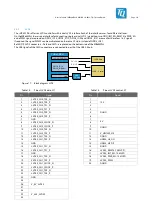
3.1.4
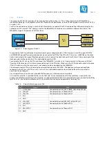
RTC backup
In case of power failure or power down, a lithium battery type CR2032 on the MBa8MPxL supplies the RTC on the TQMa8MPxL,
which can be supplied with 2.1 V to 3.7 V, typical 3.0 V. The TQMa8MPxL features an i.MX 8M Plus-internal RTC or a discrete RTC
PCF85063A. The RTC is supplied in either way.
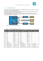
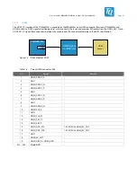
3.1.5
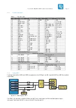
Temperature sensor
For temperature monitoring on the TQMa8MPxL and the MBa8MPxL, there is one SE97BTP sensor each.
The sensors are connected to I2C1; see Table 4. The I
2
C address of the sensor on the MBa8MPxL can be adapted by rearranging
0 Ω bridges. When changing the address, care must be taken to avoid address conflicts with existing I
2
C devices.
The assembly options are documented in the MBa8MPxL schematics.
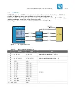
The temperature sensor D1 is located on the top side of the MBa8MPxL; see Figure 2.
Table 5:
Temperature sensor SE97BTP, D1
Manufacturer
Device
Resolution
Accuracy
Temperature range
NXP
SE97BTP
11 bits
Max. ±1 °C
+75 °C to +95 °C
Max. ±2 °C
+40 °C to +125 °C
Max. ±3 °C
–40 °C to +125 °C
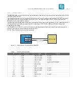
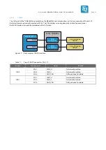
3.1.6
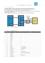
Fan
Depending on the load of the CPU and other module components, it may be necessary to use a fan for active cooling in addition
to the use of a heat sink. A corresponding circuit is provided on the MBa8MPxL.
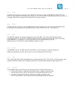
The RPM signal of the fan is connected to GPT2_CLK, the PWM signal for speed control to PWM3. Both are 3.3 V signals.
The FAN PWR signal for switching the fan is connected to the module as 1.8 V GPIO signal GPIO4_IO27.
Table 6:
Pinout fan connector, X24
Pin
Signal
Remark
1
DGND
–
2
V_FAN
12 V via R249 on MBa8MPxL (default), optional 5 V via R250 on MBa8MPxL
3
RPM
GPT2_CLK of TQMa8MPxL, 3.3 V
4
PWM
PWM3 of TQMa8MPxL, 3.3 V


