background image


II 

FCC STATEMENT 


This equipment has been tested and found to comply with the 
limits for a Class B digital device, pursuant to part 15 of the FCC 
Rules. These limits are designed to pro-vide reasonable 
protection against harmful interference in a residential 
installation. This equipment generates, uses and can radiate 
radio frequency energy and, if not in-stalled and used in 
accordance with the instructions, may cause harmful 
interference to radio communications. However, there is no 
guarantee that interference will not occur in a particular 
installation. If this equipment does cause harmful interference to 
radio or television reception, which can be determined by turning 
the equipment off and on, the user is encouraged to try to 
correct the interference by one or more of the following 
measures: 

¾

  Reorient or relocate the receiving antenna. 

¾

  Increase the separation between the equipment and 

receiver. 

¾

  Connect the equipment into an outlet on a circuit different 

from that to which the receiver is connected. 

¾

 Consult the dealer or an experienced radio/ TV technician for 

help. 

This device complies with part 15 of the FCC Rules. Operation is 
subject to the following two conditions: 
1)  This device may not cause harmful interference. 
2)  This device must accept any interference received, including 

interference that may cause undesired operation.


Summary of Contents for TL-SG1016

Page 1: ...User Guide TL SG1016 TL SG1024 16 24 port Gigabit Ethernet Switch Rev 2 0 0 7106500823...

Page 2: ...s are trademarks or registered trademarks of their respective holders No part of the specifications may be reproduced in any form or by any means or used to make any derivative such as translation tra...

Page 3: ...ment does cause harmful interference to radio or television reception which can be determined by turning the equipment off and on the user is encouraged to try to correct the interference by one or mo...

Page 4: ...measures Package Contents The following contents should be found in your package One TL SG1016 TL SG1024 Switch One power cord This User Guide Rubber footpads for Desk mount Rack mount kit for install...

Page 5: ...SG1016 TL SG1024 features a non blocking switching architecture that forwards and filters packets at full wire speed for maximum throughput MAC address auto learning and auto aging IEEE802 3x flow con...

Page 6: ...ets at full wire speed for maximum throughput Supports MAC address auto learning and auto aging LED indicators for monitoring power link speed and activity Rack mountable steel case Internal power sup...

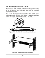
Page 7: ...ountable steel case of Electronic Industries Association Turn off all the equipment connected to the Switch before mounting it in the rack then rivet the two L brackets onto each side of the Switch fa...

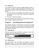
Page 8: ...check the power supply and connection Chapter 3 Identifying External Components This Chapter describes the front panel rear panel and LED indicators of the Switch TL SG1016 and TL SG1024 just differ i...

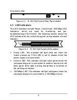
Page 9: ...of each indicator Figure 3 3 TL SG1024 Switch LEDs sketch Power LED This indicator will light solid red when the Switch powers up If the LED is not lit please check the power supply and connection Lin...

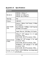
Page 10: ...Duplex 200Mbps Full Duplex Data Transfer Rate Gigabit Ethernet 2000Mbps Full Duplex 10Base T UTP category 3 4 5 cable maximum 100m EIA TIA 568 100 STP maximum 100m 100Base TX UTP category 5 5e cable...

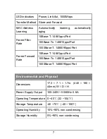
Page 11: ...Filter Rate 1000Base T 1488095pps Port 10Base T 14881pps Port 100Base Tx 148810pps Port Frame Forward Rate 1000Base T 1488095pps Port Environmental and Physical Dimensions 17 3 7 1 1 7in 440 180 44mm...

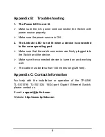
Page 12: ...esponding port Make sure that the cable connectors are firmly plugged into the Switch and the device Make sure the connected device is turned on and working well The cable must be less than 100 meters...

Reviews: