background image

Error! AutoText entry not defined.


Error! AutoText entry not defined.

 User Guide 


23 


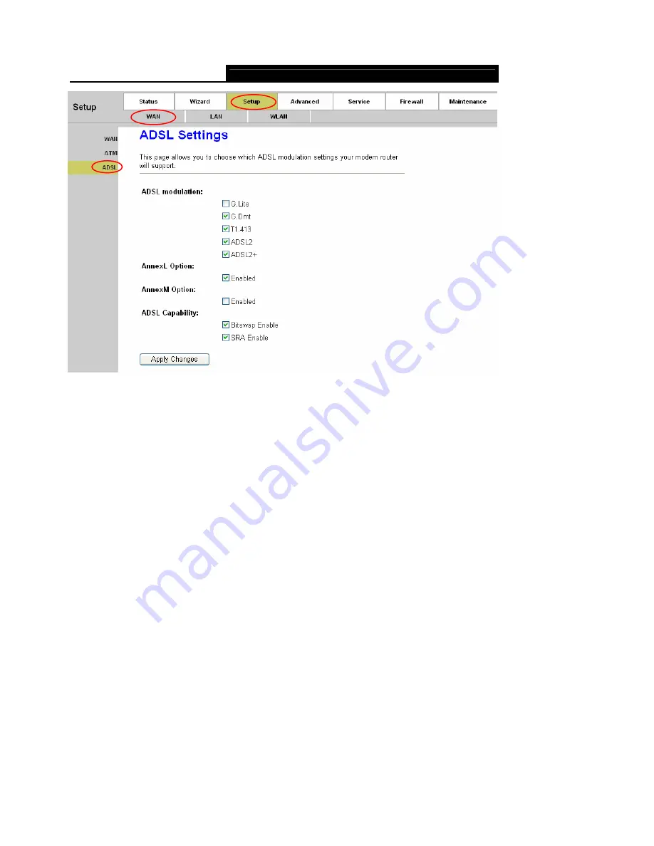
Figure 4-6 

After configuration, click 

Apply Changes

 button to save your changes. 


Note:


After saving your configuration, you need to click the 

Save

 button on the left panel to make your 

configuration take effect. 

4.2.2  LAN 

4.2.2.1  LAN 

Choose “

Setup→LAN→LAN

” menu, and you will see the LAN Interface Setup screen (shown in 

Figure 4-7). Here you can change IP address, subnet mask and other parameters for LAN 

interface. 

Summary of Contents for TD854W

Page 1: ...TD854W 150Mbps Wireless N ADSL2 Modem Router Rev 1 0 0 1910010472...

Page 2: ...antee that interference will not occur in a particular installation If this equipment does cause harmful interference to radio or television reception which can be determined by turning the equipment...

Page 3: ...onal restrictions This device is intended for home and office use in all EU countries and other countries following the EU directive 1999 5 EC without any limitation except for the countries mentioned...

Page 4: ...300 328 V1 7 1 2006 ETSI EN 301 489 1 V1 8 1 2008 ETSI EN 301 489 17 V2 1 1 2009 EN60950 1 2006 Recommendation 1999 519 EC EN62311 2008 Directives 2004 108 EC The above product is in conformity with t...

Page 5: ...ion Environment 6 2 5 Connecting the Modem Router 6 Chapter 3 Quick Installation Guide 9 3 1 Configure PC 9 3 2 Login 12 Chapter 4 Software Configuration 16 4 1 Status 16 4 1 1 Device Info 16 4 1 2 St...

Page 6: ...Filter 66 4 5 2 IP Port Filter 67 4 5 3 URL Filter 69 4 5 4 ACL 70 4 6 Maintenance 73 4 6 1 Update 73 4 6 2 Password 76 4 6 3 System Restart 76 4 6 4 Time 77 4 6 5 Log 78 4 6 6 Diagnostic 79 Appendix...

Page 7: ...50Mbps Wireless N ADSL2 Modem Router One Power Adapter for TD854W 150Mbps Wireless N ADSL2 Modem Router Quick Installation Guide One RJ45 cable Two RJ11 cables One ADSL splitter One Resource CD which...

Page 8: ...riendly help messages are provided for the configuration Network and Router management is done through the Web based Utility which can be accessed through local Ethernet using any web browser ADSL The...

Page 9: ...Proxy Snooping Protection against Denial of Service attack IP Packet filtering MAC filtering URL filtering IP QoS Dynamic DNS UPnP support System log support can record the state of the router Remote...

Page 10: ...rnet Off There is no successful Internet connection or the modem router is operating in Bridge mode Please refer to Note 2 for troubleshooting On Wireless is enabled but no data is being transmitted F...

Page 11: ...n with your ISP and make sure everything have been input correctly Refer to 4 1 1 Device Info and 4 2 1 WAN for more information 2 2 The Back Panel Figure 2 2 ADSL Through the port you can connect the...

Page 12: ...n Environment The Product should not be located where it will be exposed to moisture or excessive heat Place the Router in a location where it can be connected to the various devices as well as to a p...

Page 13: ...ess the Internet and make calls at the same time The external splitter has three ports LINE Connect to the wall jack PHONE Connect to the phone sets MODEM Connect to the ADSL LINE port of TD854W Plug...

Page 14: ...Error AutoText entry not defined Error AutoText entry not defined User Guide 8 Figure 2 4...

Page 15: ...he TD854W or connect your adapter to a Hub Switch which has connected to the Router you need to configure your PC s IP address Follow the steps below to configure it Step 1 Click the Start menu on you...

Page 16: ...Error AutoText entry not defined Error AutoText entry not defined User Guide 10 Figure 3 2 Step 3 Select General tab highlight Internet Protocol TCP IP and then click the Properties button...

Page 17: ...ress automatically and Obtain DNS server address automatically in the screen above Now you can run the Ping command in the command prompt to verify the network connection Please click the Start menu o...

Page 18: ...your PC s adapter should be lit 2 Is the TCP IP configuration for your PC correct If the Router s IP address is 192 168 1 1 your PC s IP address must be within the range of 192 168 1 2 192 168 1 254 3...

Page 19: ...see the next screen Figure 3 8 Step 2 Configure the Router with the information provided by your ISP including VPI VCI Connection Mode and the following parameters Take PPPoE for example you need to e...

Page 20: ...ed to create a name for your wireless network It s recommended that the name be unique and easy to remember You can also keep default without the device being affected Select an Encryption and Authent...

Page 21: ...WLAN is enabled the wireless function will be available even without the external antenna because of an additional printed antenna To adopt the wireless security protection measures please refer to S...

Page 22: ...bmenus will be available after you click one of the main menus On the center of the Web based Utility there are the detailed configurations or status information To apply any settings you have altered...

Page 23: ...not defined Error AutoText entry not defined User Guide 17 Figure 4 1 Click the Refresh button to refresh immediately 4 1 1 2 ADSL Choose Status Device Info ADSL menu and you will be able to view the...

Page 24: ...t entry not defined User Guide 18 Figure 4 2 Click the Retrain button to retrain the information again Click the Refresh button to refresh immediately 4 1 2 Statistics Choose Status Statistics menu an...

Page 25: ...4 1 3 Wizard Please refer to 3 2 Login 4 2 Setup Choose Setup you can see the next submenus WAN LAN and WLAN Click any of them and you will be able to configure the corresponding function 4 2 1 WAN 4...

Page 26: ...8 different virtual circuits from your ISP You need to activate the VC to take effect Click this icon to enter the VC modification page Besides some advanced settings can be configured there Click th...

Page 27: ...net by clicking the Connect or Disconnect button at the bottom of this page Idle Time min Specifies the idle time for Connect on Demand type WAN IP Settings These parameters are only available for 148...

Page 28: ...Quality of Service types for the Virtual Circuit including UBR Unspecified Bit Rate CBR Constant Bit Rate and nrt VBR Variable Bit Rate and rt VBR Please note that the selection of QoS type will lead...

Page 29: ...ave your changes Note After saving your configuration you need to click the Save button on the left panel to make your configuration take effect 4 2 2 LAN 4 2 2 1 LAN Choose Setup LAN LAN menu and you...

Page 30: ...ult value is 255 255 255 0 Secondary IP If you enable the Secondary IP you should configure another IP address and subnet mask for the LAN interface IGMP Snooping You can enable or disable the IGMP Sn...

Page 31: ...button to save your changes Note After saving your configuration you need to click the Save button on the left panel to make your configuration take effect 4 2 2 2 DHCP Choose Setup LAN DHCP menu and...

Page 32: ...equest IP addresses and the DHCP server that assigns the addresses Each of the device s interfaces can be configured as a DHCP relay In this mode the DHCP requests from local PCs will be forwarded to...

Page 33: ...e assigned dynamic IP After the dynamic IP address has expired the user will be automatically assigned a new one The default is 1440 minutes Domain Name Specify a user friendly name to refer to the gr...

Page 34: ...HCP client In Figure 4 12 we suppose 11 as PC s option60 After configuration click Apply Changes button to save your changes Note After saving your configuration you need to click the Save button on t...

Page 35: ...r configuration you need to click the Save button on the left panel to make your configuration take effect 4 2 3 WLAN There are seven submenus under the WLAN menu Basic MSSID Security Access Control A...

Page 36: ...y of the characters on the keyboard Make sure this setting is the same for all stations in your wireless network Type the desired SSID in the space provided Channel Width Select the width you want to...

Page 37: ...guration take effect 4 2 3 2 MSSID Choose Setup WLAN MSSID menu and you will see the Wireless Multiple BSSID Setup screen shown in Figure 4 15 Here you can configure the parameters for the virtual acc...

Page 38: ...detect the SSID broadcast by the Router To broadcast the Router s SSID select Enable If you don t want to broadcast the Router s SSID select Disable Relay Blocking Authentication Type Select an authe...

Page 39: ...s select WEP from the Encryption drop down list The options available will change to offer the appropriate settings Figure 4 17 SSID TYPE Select the desired wireless network to configure the security...

Page 40: ...the authentication check the box and then set the port IP address and password for the authentication radius server Click Apply Changes to save your configuration Click Close to close the screen and...

Page 41: ...it block data encryption WPA Authentication Mode Options available are Enterprise RADIUS and Personal Pre Shared key Select the desired mode and then options will change to offer the appropriate confi...

Page 42: ...llow Listed only the client on the list will be able to connect to you access point if the mode is Deny Listed these wireless clients on the list will not be able to connect to you access point Click...

Page 43: ...mes to a particular receiving station and negotiates the sending of a data frame After receiving an RTS the wireless station responds with a Clear to Send CTS frame to acknowledge the right to begin t...

Page 44: ...y Changes button to save your changes Note After saving your configuration you need to click the Save button on the left panel to make your configuration take effect 4 2 3 6 QSS Back to LED Explanatio...

Page 45: ...QSS and the Push Button Configuration PBC method you can add it to the network by PBC with the following two methods Method One Step 1 Press the QSS button on the front panel of the Router or click S...

Page 46: ...reen of Wireless Adapter Method Two Step 1 Press the QSS button on the front panel of the Router or click Start PBC button in Figure 4 22 Step 2 For the configuration of the wireless adapter please ch...

Page 47: ...n of Wireless Adapter Step 3 Wait for a while until the next screen appears Click Finish to complete the QSS configuration The QSS Configuration Screen of Wireless Adapter 2 PIN code If the wireless a...

Page 48: ...adapter please choose Enter a PIN into my access point or a registrar in the configuration utility of the QSS and get the PIN code on the screen as below then click Next The QSS Configuration Screen...

Page 49: ...e configuration of the wireless adapter please choose Enter a PIN from my access point in the configuration utility of the QSS as below and enter the PIN code of the Router into the Access Point PIN f...

Page 50: ...f changes are made after clicking Apply Changes button a Save button will appear on the left panel You need to click the Save button to make your changes take effect 4 3 Advanced Choose Advanced you c...

Page 51: ...the next hop through which traffic will forward the destination Interface Select the interface to which a static route is to be applied Click the Add Route button to add the new route in the Static Ro...

Page 52: ...r device Click the Add button to add a RIP configuration to the Rip Config List Click the Delete button to delete it The RIP Config List shows the current RIP setting of the device Note After adding a...

Page 53: ...the left panel You need to click the Save button to make your changes take effect 4 3 2 2 Virtual Server Choose Advanced NAT Virtual Server and then you can configure the Virtual Server in the screen...

Page 54: ...e to offer the configuration WAN Interface The interface on which the virtual server used on WAN side WAN IP Address The IP address which the virtual server used on WAN side You can access this IP and...

Page 55: ...t Virtual Server Forwarding Table Step 5 Click Save button on the left panel to make your configuration take effect 4 3 2 3 ALG Choose Advanced NAT ALG and then you can configure the ALG settings in t...

Page 56: ...ble or disable the port trigger function on the device After selecting click the Apply Changes button to save your configuration Application Type You can select the service from the Usual Application...

Page 57: ...mapping rules in the screen as shown in Figure 4 31 NAT IP mapping allows you to configure one IP pool for specified source IP address from LAN so a packet whose source IP is in range of the specifie...

Page 58: ...Global Start IP Current NAT IP MAPPING Table This displays the information about the Mapping address Note If changes are made after clicking Apply Changes button a Save button will appear on the left...

Page 59: ...2 1p or DSCP Schedule Mode The schedule mode of the IP QoS function it can be strict prior or WFQ 4 3 2 1 Strict prior Traffic with different priority will be send by its priority the higher priority...

Page 60: ...rc Mask The source mask of the rule Dest IP The destination IP address of the rule Dest Mask The destination mask of the rule Src Port The source port number of the rule If the Protocol filed is not b...

Page 61: ...SCP or 802 1p tag The traffic matches the rule will be added or modified the mark Note If you select 802 1p tag please make sure 802 1q is enabled in specified WAN interface otherwise 802 1p tag will...

Page 62: ...tag The number of 802 1p tag Send priority The priority to transmit The traffic matches the 802 1p filed will be assigned this priority Modify Click this button to modify your configuration 802 1p rul...

Page 63: ...l be assigned this priority Dscp rule list Shows the current rules on the device 4 3 4 CWMP Choose Advanced CWMP you can configure the CWMP function in the screen shown in Figure 4 36 Here you may cha...

Page 64: ...ting to the ACS Periodic Inform Enable When this field is enabled the device will send an Inform RPC to the ACS server at the system startup and will continue to send it periodically at an interval de...

Page 65: ...s multiple interface groups up to five interface groups are supported including one default group Traffic coming from one interface of a group can only be flowed to the interfaces in the same interfac...

Page 66: ...pping group as follow steps 1 Select a group Group 1 Group 2 Group3 or Group 4 from the table then you can see the available interface LAN and WAN and grouped interface list 2 Select interfaces from t...

Page 67: ...oose Service you can see the next submenus Click any of them and you will be able to configure the corresponding function 4 4 1 IGMP Proxy Choose Service IGMP Proxy menu you can configure the IGMP pro...

Page 68: ...gure 4 40 UPnP Universal Plug and Play is a distributed open networking standard that uses TCP IP for simple peer to peer network connectivity between devices An UPnP device can dynamically join a net...

Page 69: ...gement protocol which uses the UDP protocol on port 161 to communicate between the clients and servers The router can be managed locally or remotely by SNMP protocol Figure 4 41 Enable SNMP Choose to...

Page 70: ...ace via the auto configuration mechanism Set DNS Manually Select this option and then you need to configure the DNS IP address manually Note If changes are made after clicking Apply Changes button a S...

Page 71: ...nterface over which your device will be accessed Enable Check to enable the registration account for the DDNS server DynDns Settings Username Username assigned by the DDNS provider Password Password a...

Page 72: ...in Figure 4 44 In order to management your local network better you can use the MAC address filter function to control the internet access Here you can set the MAC filtering rules Figure 4 44 Outgoing...

Page 73: ...e destination MAC address of the filter entry Empty means matching any source MAC address Add Click this button to add your rule into Current MAC Filter Table Current MAC Filter Table It shows the cur...

Page 74: ...The direction of this entry it can be upstream and Downstream Source IP Address Mask Address The source IP address and mask address of the entry Dest IP Address Mask Address The destination IP addres...

Page 75: ...ify which site can t be accessed based on URL to secure or restrict your local network Figure 4 46 URL Blocking Capability Enable or disable the URL filtering function If it is enabled the access to t...

Page 76: ...utton a Save button will appear on the left panel You need to click the Save button to make your changes take effect 4 5 4 ACL Choose Firewall ACL you can see the next screen shown in Figure 4 47 ACL...

Page 77: ...it is enabled only the hosts on the Current ACL Table can access the specified services IP Address The IP address of the host 0 0 0 0 means any IP Service Allowed LAN side The allowed services which...

Page 78: ...IP Address If it is Interface you should specify a WAN interface for this ACL entry If the WAN setting is IP Address you should specify the IP address of the host on WAN side Service Allowed You can s...

Page 79: ...you will be able to configure the corresponding function 4 6 1 Update 4 6 1 1 Firmware Update Choose Maintenance Update Firmware Update you can upgrade the firmware of the Router in the screen shown i...

Page 80: ...t configurations so please back up the router s current settings before you upgrade its firmware 2 Do not turn off the router or press the Reset button while the firmware is being upgraded 3 The route...

Page 81: ...ined User Guide 75 Figure 4 52 Step 2 Save the file as the appointed file shown in Figure 4 53 Figure 4 53 To restore the Router s settings Step 1 Click the Browse button to locate the file for the de...

Page 82: ...figure the user account of the router in the screen shown in Figure 4 54 Here you can add user account to access the web server and modify the password of the specified user Figure 4 54 4 6 3 System R...

Page 83: ...the screen shown in Figure 4 56 Simple Network Timing Protocol SNTP is a protocol used to synchronize the system time to the public SNTP server You can also configure the time manually Figure 4 56 1...

Page 84: ...Time Zone The time zone in which the device resides Get GMT Time After setting the NTP configuration correctly click this button to start the NTP function Then you can see the GMT time obtained from...

Page 85: ...ed to click the Save button to make your changes take effect 4 6 6 Diagnostic The router provides several useful diagnostic tools 4 6 6 1 Ping Choose Maintenance Diagnostic Ping you can ping a specifi...

Page 86: ...ute command timeout Datasize Data size of the trace route packet MaxHopCount The maximum hop count Interface The interface to which the trace route is to be applied For example you can set the host to...

Page 87: ...5 Segment F5 End to End F4 Segment or F4 End to End VPI The VPI number you want to do the loopback diagnostics VCI The VCI number you want to do the loopback diagnostics 4 6 6 4 ADSL Diagnostic Choose...

Page 88: ...he diagnostic and then wait several minutes later you will see the test result 4 6 6 5 Diag Test Choose Maintenance Diagnostic Diag Test you can select an interface to run diagnostic in Figure 4 64 Th...

Page 89: ...utoText entry not defined Error AutoText entry not defined User Guide 83 Figure 4 64 Click the Run Diagnostic Test button to start the test and then wait several times later you can see the diagnostic...

Page 90: ...o Negotiation RJ45 ports Auto MDI MDIX One RJ11 port LEDs Power ADSL Internet WLAN 1 2 3 4 LAN QSS Network Medium 10Base T UTP category 3 4 5 cable 100Base TX UTP category 5 Max line length 6 5Km Data...

Page 91: ...to re configure the router 2 What can I do if I don t know or forgot my password 1 Restore the Router s configuration to its factory default settings If you don t know how to do that please refer to...

Page 92: ...Error AutoText entry not defined Error AutoText entry not defined User Guide 86 Click Properties Click Network Connections Right click Local Area Connection Double click Internet Protocol TCP IP...

Page 93: ...Error AutoText entry not defined Error AutoText entry not defined User Guide 87 Click OK Click OK Select Obtain an IP address automatically Select Obtain DNS server address automatically...

Page 94: ...defined Error AutoText entry not defined User Guide 88 For Windows Vista OS Go to Start Settings Control Panel and then you will see the following page Click View network status and tasks Click View...

Page 95: ...entry not defined Error AutoText entry not defined User Guide 89 Click OK Double click Internet Protocol Version 4 TCP IPv4 Select Obtain an IP address automatically Select Obtain DNS server address...

Page 96: ...xt entry not defined User Guide 90 For Windows 7 OS Go to Start Settings Control Panel and then you will see the following page Click View network status and tasks Right click Local Area Connection Cl...

Page 97: ...entry not defined Error AutoText entry not defined User Guide 91 Double click Internet Protocol Version 4 TCP IPv4 Select Obtain an IP address automatically Select Obtain DNS server address automatic...

Page 98: ...annot access the Internet please restore your Router to its factory default settings and reconfigure your Router by following the instructions of this QIG 4 Please feel free to contact our Technical S...

Page 99: ...ot defined User Guide 93 to contact our Technical Support if the problem persists Note For more details about Troubleshooting and Technical Support contact information please log on to our Technical S...

Page 100: ...s a week USA Canada Toll Free 1 866 225 8139 E mail support usa tp link com Service time 24hrs 7 days a week Germany Austria Tel 49 1805 875465 German Service 49 1805 TPLINK E mail support de tp link...

Reviews: