background image


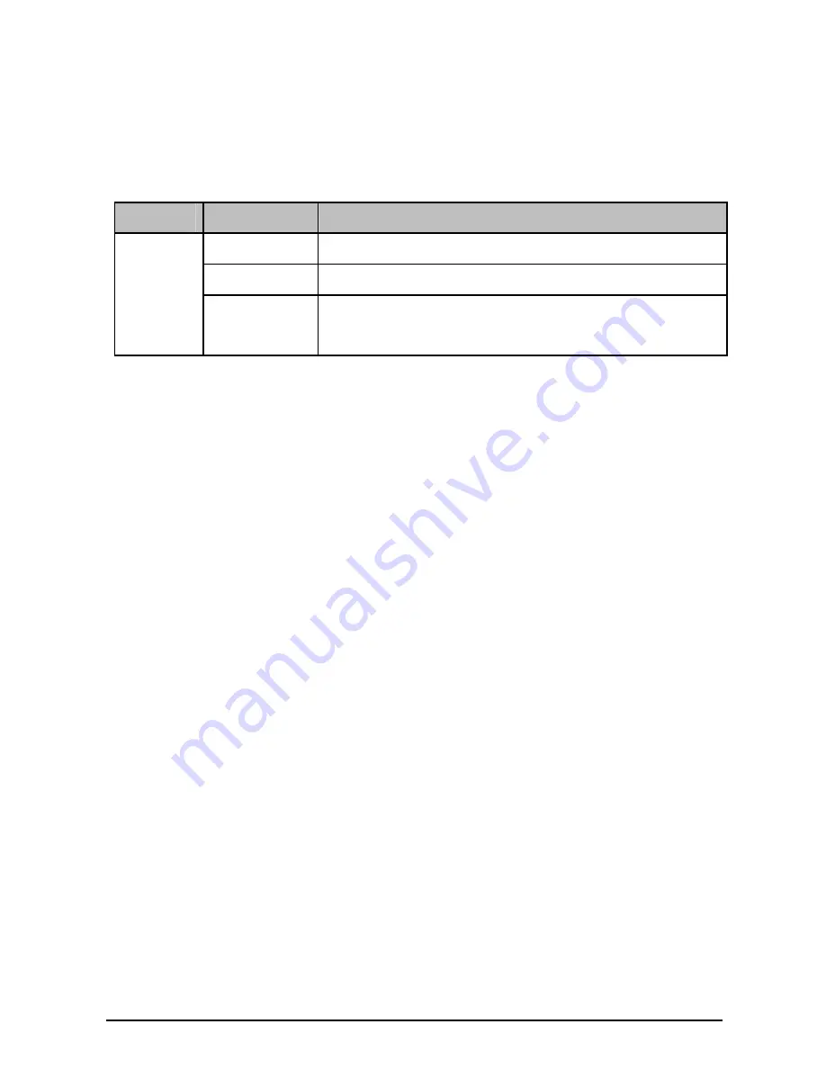
1.3  Description of LEDs 

There is an LED for each port, labeled as M1 and M2, on the 
panel of TX432. Described below: 

LED 

Status 

Description 

Off 

The port isn’t connected to any devices. 

On 

SPF+ port is connected to a device. 

M1,M2 

Blinking 

SPF+ port is connected to a device and 
transferring data. 

)

Note: 

The switch applicable to TX432 will display corresponding LEDs 
on its front panel to indicate the port status of the interface card. 
For details about the LEDs, please refer to the switch user 
guide.  

Chapter 2 

Installation 

2.1  Tools for installation 


Philips screwdriver 


ESD-preventive wrist strap 

2.2  Installing & Removing the Interface Card 


Installing the Interface Card to the switch 

1. 

Wear an ESD-preventive wrist strap, and make sure that it 
has good skin contact and is well grounded. 

2. 

Use a Phillips screwdriver to loosen the mounting screws 
of the filler panel on the interface card slot of the switch 
(T3700G-28TQ for example) and remove the filler panel, 
as shown in Figure 2-1. 

Summary of Contents for JetStream TX432

Page 1: ...Installation Guide TX432 JetStream 10 Gigabit 2 Port SFP Module REV1 0 1 7106504459...

Page 2: ...are trademarks or registered trademarks of their respective holders No part of the specifications may be reproduced in any form or by any means or used to make any derivative such as translation tran...

Page 3: ...cause harmful interference to radio communications Operation of this equipment in a residential area is likely to cause harmful interference in which case the user will be required to correct the inte...

Page 4: ...power button the power button is one of the way to shut off the product When there is no power button the only way to completely shut off power is to disconnect the product or the power adapter from...

Page 5: ...verview of the Product JetStream 10 Gigabit 2 Port SFP Module TX432 is an interface card providing two 10G SFP ports It is applicable to multiple TP LINK switch models Figure 1 1 Appearance of TX432 F...

Page 6: ...cable provided by TP LINK For details about the supported SFP transceivers and SFP cables please refer to the table below Transceiver Cable Central wavelength Connector Interface cable Max transmissi...

Page 7: ...te the port status of the interface card For details about the LEDs please refer to the switch user guide Chapter 2 Installation 2 1 Tools for installation Philips screwdriver ESD preventive wrist str...

Page 8: ...the slot guide rail until the interface card is flush with the switch as shown in Figure 2 2 Figure 2 2 Install an interface card 2 4 Tighten the captive screws with a Phillips screwdriver to fix the...

Page 9: ...tly with your hand while the switch is in operation After removing an interface card if no new interface card is to be installed please install the filler panel as soon as possible to prevent dust fro...

Page 10: ...ht at the optical port of TX432 when it is operating because the optical fiber beam is of high energy and thus will do great harm to the retina Looking straight at the optical fiber beam could do grea...

Page 11: ...e IEEE 802 3aq SFF 8431 Safety Emissions FCC CE Max Power Consumption 6 57w with Fiber LED M1 M2 Operating Temp 0 50 32 122 Storage Temp 40 70 40 158 Operating Humidity 10 90 RH Non condensing Storage...

Page 12: ...465 German Service 49 1805 TPLINK 43 820 820 360 Fee Landline from Germany 0 14EUR min Landline from Austria 0 20EUR min E mail support de tp link com Service time Monday to Friday 09 00 to 12 30 and...

Reviews: