
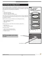


FULLY OPEN
4“ OPEN
2“ OPEN
1“ OPEN
20’
30’
40’
48’
0
5
10
15
20
0
Fig. #45a
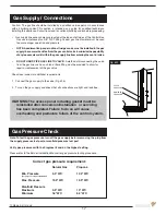
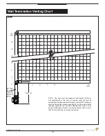
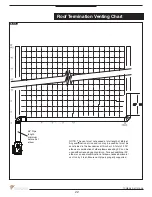
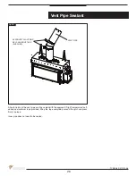
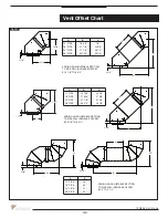
The vent restrictor is located on the underside of the firebox top. The unit leaves the
factory with the vent restrictor open. The restrictor is built into the appliance for secondary
air flow adjustment. Adjustment enables tuning the airflow for optimum flame appearance
and performance for a wide variety of vent configurations.
Setting:
• determine the vent height
• determine the vent horizontal length
• from the chart determine the restrictor position
Refer to the chart in Fig. #45 for the correct position of restrictor for the vent configuration
of your installation. Restrictor positions are based upon lab tests. The ideal position may
vary slightly with installation.
Restrictor position is too closed if the flame has the following characteristics:
• Flame is excessively tall and lifting.
• Flame lacks movement.
• Flame soots.
Restrictor position is too open if the flame has the following characteristics:
• Flame height is low.
• Flame has excessive movement.
To adjust the restrictor:
• Loosen the screw holding the restrictor.
• Move the restrictor to its intended opening.
• Re-tighten the screw.
WALL AND ROOF
TERMINATION
RESTRICTOR POSITION
Fig. #45
CAUTION: The vent restrictor must be fully open
when using the TCVT.PVB1 power vent kit to vent
this fireplace.
VENT RESTRICTOR
OPENING
27
TCWS38_D 011214-48
Vent Restrictor Adjustment
Summary of Contents for TCWS38
Page 43: ...Fig 76 Wiring Diagram 43 TCWS38_D 011214 48 ...
Page 45: ...45 TCWS38_D 011214 48 ...
Page 46: ...46 TCWS38_D 011214 48 ...
Page 47: ......


