

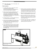

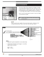
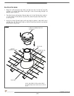

The gas control system is located on the right hand side of the firebox behind an access
panel and the decorative firebox panel (if installed). The fireplace is operated via a wall
control and a hand held remote control unit.
The wall control is connected to the fireplace by a 40 ft. communication cable supplied
with the fireplace.
Installation
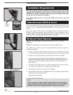
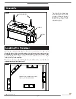
1. Place the fireplace in the desired location.
2. Remove the window from the fireplace.
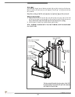
3. Remove access panel from right hand side of the firebox (Fig #23).
4.
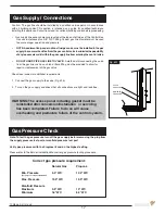
Connect 110 V. AC electrical supply to the wires installed inside the junction box
(Fig #24). The fireplace is rated at 110 volts, 60Hz, 0.25A. The optional power vent kit
is rated at 115 volts, 60Hz, 1.8A.
The electrical wires can be accessed from both inside and outside the junction box by
removing one of the two small access panels (Figs #24 & 25).
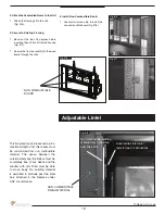
5.
Attach the wall switch to the framing in the desired
location (Figs #26 & 27) (40 ft is supplied with fireplace).
Fig. #24
6.
Route the wall switch control cable (supplied) as required to
the wall switch (Fig #27).
7. Attach one end of the wall switch control cable to the wall
control. (Fig #27), and the other end to the interface board
(Fig #25).
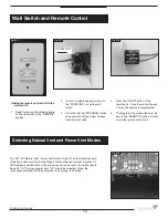
8.
Insert the 4 supplied “AA” batteries into the battery pack of the
wall switch. (Fig #28).
9. If not already installed, install the burner using the instructions
supplied with the burner kit.
10. Turn on the gas supply and check that all connections are tight
and leak free.
11. Turn on gas and electrical supplies.
12. Move the center button on the wall control (Fig #26) to the “ON”
position. The igniter will start to spark. After a short delay, the
pilot will light followed by the main burner.
Fig. #25
FIREBOX ACCESS PANEL
Fig. #23
INTERFACE BOARD
MODULE
JUNCTION BOX
REGULATOR
BOARD
TRANSFORMER
VACUUM
SWITCH
GAS CONNECTOR
OUTER ACCESS PANEL
INSIDE ACCESS
PANEL
WALL SWITCH
CONNECTOR
JUNCTION BOX
POWER
VENT
SWITCH
Electrical
Note: Installation must be performed by a qulaified
installer, service agency or gas supplier.
14
TCWS38_D 011214-48
Summary of Contents for TCWS38
Page 43: ...Fig 76 Wiring Diagram 43 TCWS38_D 011214 48 ...
Page 45: ...45 TCWS38_D 011214 48 ...
Page 46: ...46 TCWS38_D 011214 48 ...
Page 47: ......


