**
24"
*
38 1/8"
4"
* MANTEL CLEARANCE
A
9”
B
6”
C
3”
** MANTEL DEPTH
D
12”
E
6 3/4”
F
1 1/2”
MANTEL CLEARANCE
CHART
Minimum Clearances:
Side standoffs .................................................... 0 in. (0 mm)
Back standoffs ................................................... 0 in. (0 mm)
Top standoffs ...................................................... 0 in. (0 mm)
Bottom of appliance ........................................... 0 in. (0 mm)
Adjacent side wall .............................................. 4 in. (102 mm)
Ceiling to appliance .......................................... 24 in. (610 mm)
*Mantel to appliance ................................... (Figure 3)
**Maximum Mantel extension ..................... (Figure 3)
Mantel support ................................................... 4 in. (102 mm)
Vertical vent pipe ........................................1 3/4" in. (45 mm)
Horizontal Vent pipe (Top, sides and bottom) 1 3/4" in. (45 mm)
MAY USE COMBUSTIBLE
FACING MATERIAL IN THIS
AREA
NON-COMBUSTIBLE
FINISH MATERIAL
SEE FIG #14 & 15
NON-COMBUSTIBLE ZONE.
DO NOT INSTALL ANY COMBUSTIBLE
MATERIAL, ELECTRICAL WIRING OR GAS
PLUMBING IN THIS AREA.
COMBUSTIBLE FRAMING AND
FINISH WALL ABOVE STANDOFFS
STANDOFFS
STEEL FRAMING
FIREPLACE FRONT
TOP OF LINTEL BAR
A
B
C
D
E
F
24”
32 1/2”
4”
MANTEL
ADJACENT WALL
OR MANTEL
SUPPORT
CEILING
UNIT MAY BE RECESSED UP TO 4 1/2” WITH
NON-COMBUSTIBLE MASONRY TYPE
MATERIAL
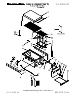
Figure 3:
TC 36 Mantle clearances.
Figure 4:
TC 36D Mantle.
6
TC36_D & TC36_DAR_101215-52
5056.427D
Minimum Clearances to Combustible Material