7
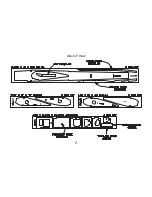
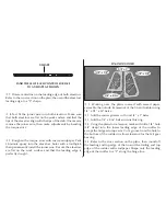
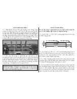
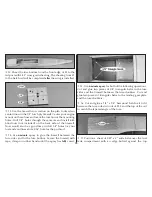
V-SHAPE
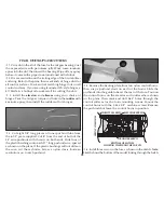
SAND THE LE OF EACH CONTROL SURFACE
TO A V-SHAPE AS SHOWN
❍
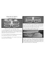
7. Draw a centerline on the leading edge of both elevators.
Refer to the cross section on the plan, then sand the elevator’s
leading edge to a “V” shape.
❍
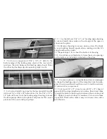
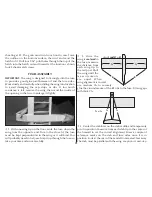
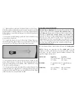
8. Test fit the joiner wire into both elevators. Make sure
that both elevators are flat on the work surface and that the
tips of the elevators align with the tips of the stab. If necessary,
remove the joiner wire, then make adjustments by bending
the torque arms.
❍
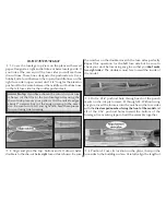
9. Roughen the torque arms with coarse sandpaper. Pack
30-minute epoxy into the elevator’s holes with a toothpick,
then permanently install the joiner wire. Be sure the elevators
are flat on the work surface and that the leading edge is
perfectly straight.
FIN AND RUDDER
❍
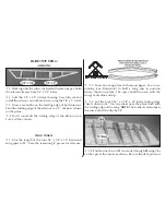
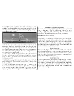
1. Working over the plans covered with waxed paper,
assemble the outside framework of the fin and rudder using
1/4" x 1/2" x 30" balsa.
❍
2. Add the corner gussets cut from 1/4" x 1" balsa.
❍
3. Add the 1/4" x 3/16" balsa internal bracing.
❍
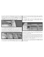
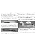
4. Using the plans for reference, mark and drill a 1/8" hole
(3/4" deep) into the lower leading edge of the rudder to
accept the tail gear torque arm. Cut a groove from the hole to
the bottom of the rudder to allow clearance for the tail gear
bearing.
❍
5. Refer to the cross section on the plans, then round off
the leading and top edge of the fin and the trailing and top
edge of the rudder with sandpaper. Shape only the leading
edge of the rudder to a “V” along the hinge line.
Summary of Contents for UPROAR
Page 5: ...5 DIE CUT PAGE ...


