18
FINAL HOOKUPS AND CHECKS
❍
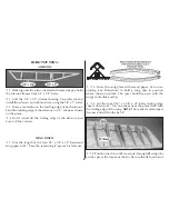
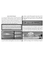
1. Cut a slot in the aft of the fuse for the tail gear bearing. Coat
the exposed wire with petroleum jelly. Work some 6-minute
epoxy into the slot, then insert the bearing. Wipe off any epoxy
before it cures with a paper towel moistened with alcohol.
❍
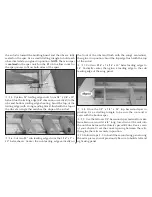
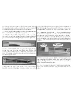
2. Draw a centerline on the trailing edge of the fin, stabilizer
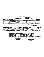
and wing. Refer to the plans, then mark and cut hinge slots for
all control surfaces. Mark and cut matching hinge slots on all
control surfaces. If you are using laminated CA style hinges, a
#11 blade in a hobby knife works well for cutting the slots.
❍
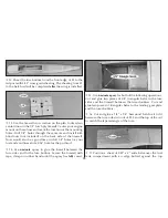
3. Install the
elevators
and
ailerons
using your choice of
hinges. Pack the tail gear torque rod hole in the
rudder
with
6-minute epoxy, then install the rudder with its hinges.
❍
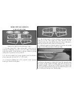
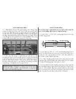
4. Cut eight 1/8" long pieces of inner pushrod tube from
the 6-1/2" piece supplied. Cut 8" from the end of both of the
35" wire pushrods with threads on both ends. Slide four of
the plastic bushings onto each 27" long pushrod wire, spaced
as shown on the plans. If the plastic bushings will not slide on
the wire, cut them shorter. Screw a nylon clevis fourteen
revolutions on to each pushrod.
❍
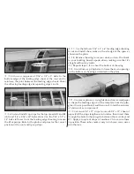
5. Remove the backing plate from two nylon control horns,
then snap a pushrod clevis on each of the horns. Slide the
pushrods into the guide tubes at the rear of the fuse. Position
the control horns on the elevator and rudder where shown
on the plans, then mark and drill 5/64" holes through the
control surfaces for the horn mounting screws. Mount the
control horns with the 2-56 x 5/8" machine screws. Remove
the pushrods but leave the control horns in position.
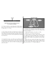
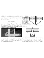
THROTTLE SERVO
ELEVATOR SERVO
RUDDER SERVO
FRONT OF MODEL
BOTTOM OF MODEL
LOOKING THROUGH THE HATCH
❍
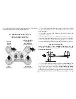
6. Install three servos in the fuse as shown in the sketch.
Note:
Sketch shows the bottom of the model looking through the hatch.
Summary of Contents for UPROAR
Page 5: ...5 DIE CUT PAGE ...

