background image

21

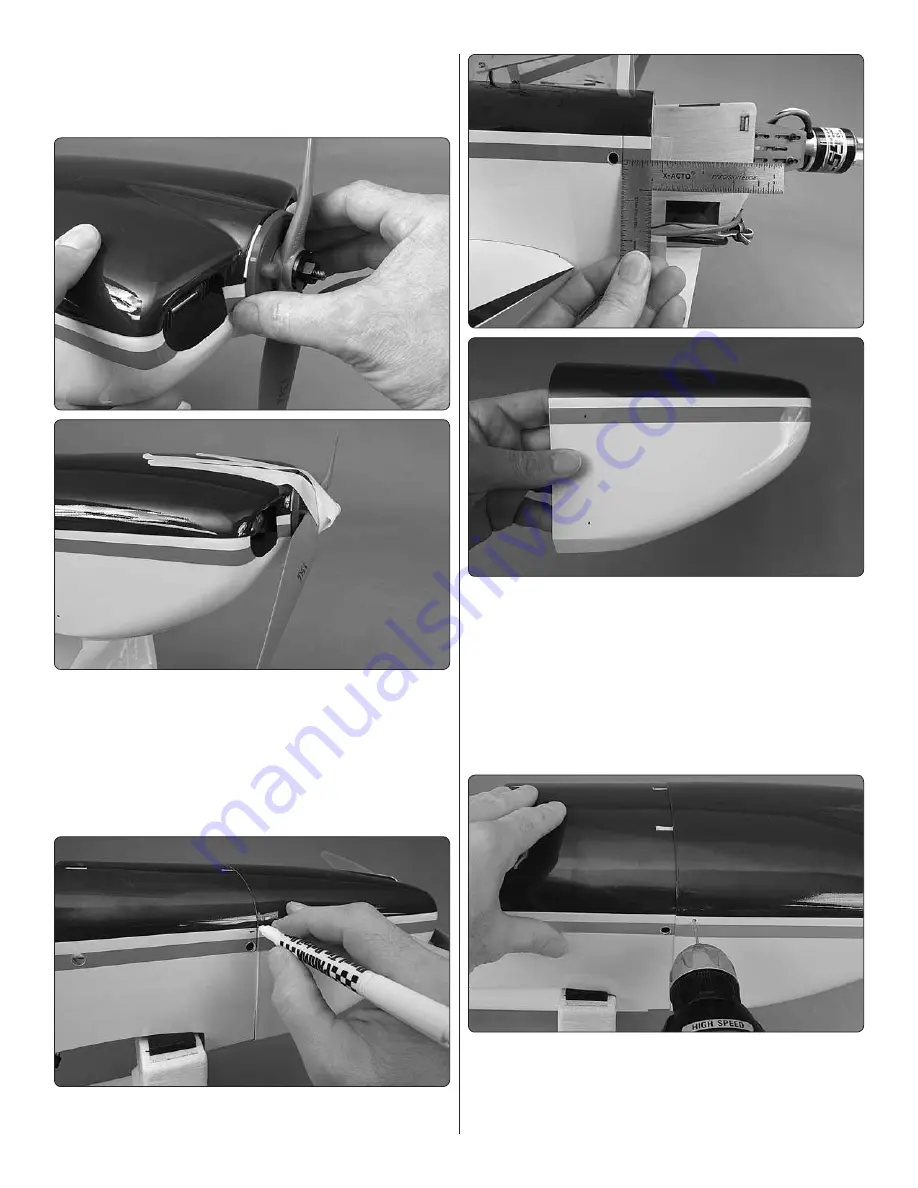
 2. Position the cowl onto the fuselage over the engine/motor 

and install the spinner back plate onto the prop shaft with a 
prop and prop nut. (For glow engines, temporary removal of 
the muffl er and needle valve may be required to fi t the cowl.).

 3. Insert shims from balsa or card stock the thickness of the 

desired spinner gap (approximately 3/32" [2.5mm]) between 
the front of the cowl and the back plate of the spinner and 
tightly tape the spinner to the cowl. 

Note:

 If you’re using a 

brushless motor with the Great Planes adjustable brushless 
motor mount, no need for the shims; after the cowl has been 
mounted, simply adjust the mount to move the motor forward 
until the desired spinner gap has been achieved.

 4. Use a fi ne-point felt-tip pen to mark the aft edge of 

the cowl onto both sides of the fuselage. Remove the cowl.

 5. Measure the distance from the lines on the fuselage to 

the middle of the cowl mount blocks. Mark dots from the aft 
edge of the cowl the distance you measured.

 6. Drill 1/16" [1.6mm] holes through the cowl at the marks.

 7. Same as before, reinstall the cowl, spinner back plate 

and shims (if used for a glow engine) and tape the cowl to 
the spinner. Make sure the cowl is accurately aligned with the 
spinner back plate and the stripes on the cowl are aligned 

with the stripes on the fuselage.

 8. Drill 1/16" [1.6mm] holes through the holes in the cowl 

into the cowl mount blocks.

 9. Remove the cowl. Enlarge the holes in the cowl with a 

3/32" [2.4mm] drill.

Summary of Contents for Ultimate

Page 1: ...repared to accept the liability associated with the use of this product the buyer is advised to return this kit immediately in new and unused condition to the place of purchase To make a warranty claim send the defective part or item to Hobby Services at the address below Hobby Services 3002 N Apollo Dr Suite 1 Champaign IL 61822 USA Include a letter stating your name return shipping address as mu...

Page 2: ... your Ultimate with a brushless electric motor you may power the receiver and servos from the BEC in the ESC so a receiver battery or on off receiver switch will be not required The Ultimate was designed for mini servos but regular servos with minimum torque of 55oz in 4 0 kg cm may be used simply by enlarging the servo mounts in the wing and fuselage Tactic TSX25 mini digital high speed 2 ball be...

Page 3: ...Brushless Electric Motor The electric setup for the Ultimate is straightforward a Great Planes ElectriFly RimFire 55 on a 6S battery in the 3800mAh range with a 75A ESC Propeller selection depends upon your preference and flying style but we preferred the APCX 16 x 8E full discussion on prop selection on page 32 A Castle Creations Edge Lite 75 is also recommended and illustrated in the instruction...

Page 4: ...e with assembly contact Product Support When reporting defective or missing parts use the part names exactly as they are written in the Kit Contents list Hobbico Product Support 3002 N Apollo Drive Suite 1 Ph 217 398 8970 ext 5 Champaign IL 61822 Fax 217 398 7721 E mail airsupport hobbico com Order No Description REPLACEMENT PARTS LIST TOWA4050 TOWA4051 TOWA4052 TOWA4053 TOWA4054 TOWA4055 TOWA4056...

Page 5: ...erheat a seam causing separation 1 Use a covering iron with a cover sock to tighten any loose covering Wherever the covering is attached to wood press down on the iron to thoroughly bond the covering to the balsa underneath Where possible reach inside the model and support sheeted areas while tightening the covering to prevent the sheeting from bending inward If you ll be using the top wing ailero...

Page 6: ... stacked on top of each other cut into small squares will come in handy for wiping off excess CA and or epoxy as you proceed with assembly For epoxy clean up later dampen the squares with denatured alcohol 9 Glue the wood dowels into the bottom wing 10 If powering your Ultimate with a glow engine fuelproof any areas that may be exposed to raw fuel or oily engine exhaust such as the openings in the...

Page 7: ...the servos separately with four channels eliminate adjusting the servos independently with end points and sub trims we just kept it simple and Y d the servos in the top wing to each other and Y d the servos in the bottom wing to each other then Y d the Y s together inside the fuselage into a single aileron channel The advantage with this option is only one servo wire coming from the top wing which...

Page 8: ...any precise angle The arms just need to be angled forward so the pushrods will be approximately perpendicular with the servo arms when connected to the control horn on the aileron 7 Cut the unused arms from the servo arm and enlarge the holes in the servo arm with a 50 070 drill for the pushrod wires Fasten the arms to the servos with the screws that came with the servos 8 Cut the covering from on...

Page 9: ... pushrods so the ailerons will be centered when the servos are centered M2 x 10 For Bottom Ailerons Only Small Control Horn Centered Behind Mounting Plate 3 If not installing aileron servos in the top wing mount a small control horn to the top surface of the bottom ailerons in the location illustrated in the image above and in the illustration on the bottom of the column to the left ASSEMBLE THE F...

Page 10: ...doing it with glue A Center the stab laterally taking measurements from both sides of the fuselage B Once the stab is centered insert pins into the trailing edge tightly against both sides of the fuselage to lock the trailing edge into place A A A A C Insert a pin into the fuselage centered over the stringer at the front of the hatch opening Use an inelastic string around the pin with a line drawn...

Page 11: ...b the model until the epoxy has hardened 7 Test fit the vertical stabilizer fin into position Make any adjustments necessary for a good fit and to make sure the fin is vertical then permanently glue it into place with 30 minute epoxy Use T pins or clamps as necessary to close any gaps between the fin and the fillet blocks Any pinholes from T pins can be reduced later with a covering iron Hinge the...

Page 12: ...h the elevator tack glue the hinges into the rudder then test fit the rudder to the fin Make any adjustments necessary for a good fit then remove the rudder and tail gear 7 Using care not to get any epoxy into the hinge points around the tail gear wire insert the hinges into the fuselage with 30 minute epoxy Add epoxy into the hole in the rudder for the arm part of the tail gear wire then fit the ...

Page 13: ...rted from the front of the guide tubes 4 Drill 1 16 1 6mm holes through the servo tray and mount the servos to the servo tray with the screws included with the servos 5 You can temporarily connect the servos to the receiver and operate the servos and adjust the length of the pushrods now or later when performing final radio setup Mount the Motor If using a glow engine skip to Mount the Engine on p...

Page 14: ...late will be 4 3 4 120mm from the firewall then use a 3 32 Allen wrench to tentatively tighten the screws on both sides of the mount to temporarily lock the halves together Mount the ESC 1 You may copy the battery and ESC installation shown in the manual or do it another way if you have a different ESC However you mount the ESC plan and test fit the battery and ESC before cutting wires or performi...

Page 15: ... the battery in the event of a crash 6 Install the battery tray making sure the front of the tray keys into the short balsa sticks right behind the firewall to hold the front of the tray down Fasten the battery tray with one of the finger turn 20 nylon bolts included Make sure the discharge wires from the ESC can reach the discharge wires from the battery CAUTION If powering the receiver and servo...

Page 16: ...ugh the mark in either case use a drill press if you have access to one to ensure the hole is perpendicular to the surface of the mount If you don t have a drill press do your best to hold the drill vertically so the hole will be perpendicular 4 If tapping threads use a 3mm tap to thread the hole if care is used you can chuck the tap in a hand drill to make the procedure easier and faster 5 Fasten...

Page 17: ...he template aligned with the crossmarks on the firewall Push a pin into the firewall through the marks in the template that align with the mounting holes in the engine mounts 12 Remove the template from the firewall Drill 1 16 1 6mm pilot holes through the firewall at the pinpoints Enlarge the holes with a 13 64 or 7 32 drill 13 Use an M4 x 20 SHCS socket head cap screw with a stack of washers and...

Page 18: ...de Option Insert the third aluminum tube through the stopper and attach another pickup line and clunk not included for a fueling defueling line so you won t have to detach the fuel line from the engine to fuel and as you will with a single line 3 Insert the stopper into the tank with the vent line at the top of the tank Write TOP on top of the tank or just insert the stopper with the vent at the s...

Page 19: ...o it s easiest to position the pushrod and servo above the tray as well The throttle servo may be installed in the servo tray next to the elevator and rudder servos but make sure the servo won t interfere with the wing bolt If the throttle servo will not fit in the servo tray perhaps the servo arm on the elevator or rudder servo could be flip flopped allowing that servo to be relocated to make roo...

Page 20: ... in the servo arm causing the throttle pushrod to bind Because of this threadlocker must be used on the thread on retainer so it does not come off 4 While we re still working under the hood mount the muffler and connect the fuel line to the carb and the vent line to the pressure tap off the muffler the dangling fuel line in the photo will be for fueling defueling Mount the Cowl Disregard the landi...

Page 21: ...nt to move the motor forward until the desired spinner gap has been achieved 4 Use a fine point felt tip pen to mark the aft edge of the cowl onto both sides of the fuselage Remove the cowl 5 Measure the distance from the lines on the fuselage to the middle of the cowl mount blocks Mark dots from the aft edge of the cowl the distance you measured 6 Drill 1 16 1 6mm holes through the cowl at the ma...

Page 22: ...e options An optional universal mounting tray is included for the receiver and or receiver battery and another optional battery tray is also included to mount a receiver battery in the nose If you ve installed an electric motor the receiver should be mounted on the bottom of the servo tray in the wing saddle so as not to interfere with installation removal of the battery tray 1 If not using the un...

Page 23: ...to cut holes in the fuselage for the switch then mount the switch Mount the Main Landing Gear 1 Fasten the wheel axles to the main landing gear with an 8mm lock nut be certain to use threadlocker on the threads as the threaded portion of the axles does not engage the nylon locking part in the nuts 1 8 3mm 1 4 6mm 2 Use a reinforced cutoff wheel and or a metal file to grind a 6mm flat spot 1 8 3mm ...

Page 24: ...cation of the wheel on the axle by moving the wheel collars then retighten tightly 5 Mount the landing gear to the fuselage with six M3 x 12 Phillips screws and M3 washers and threadlocker Attach the Belly Pan 1 Mount the bottom wing to the fuselage with the included 20 x 1 nylon wing bolts and 5 8 x 16 x 19mm wing bolt plates 2 Carefully cut just into the covering around the wing bolt plates Do n...

Page 25: ... cockpit hatch may be held to the fuselage with M3 screws and washers through both sides of the fuselage into the tabs or with the rubber band hook and a rubber band If using a glow engine the rubber band hook is not recommended so the screws should be used to retain the canopy hatch 1 If installing a pilot or if using the rubber band hook to retain the canopy hatch glue the cockpit floor doubler ...

Page 26: ...ill Trim any flashing from the inside of the canopy around the holes 8 If the canopy needs cleaning wash in warm soapy water then dry 9 Fasten the canopy with four M2 6 x 8 washer head Phillips wood screws Mount the Wings NOTE Whenever removing the wings in the future the bottom wing cannot be easily removed without first removing the top wing with the outer wing struts attached to it so whenever ...

Page 27: ...er top Front cabane Aft cabane Cross brace Hole Hole 3 Being certain to use threadlocker on all the screws loosely fasten the forward and aft cabane struts to the fuselage with four M3 x 8 Phillips screws Hint For inserting the screws the fuselage may be placed on its side and the screws can be lifted on your screwdriver through the holes 4 Loosely attach the cross braces to the cabanes with four ...

Page 28: ...ud to act as a stop nut and turn them to turn in the stud The studs should stop when they get about halfway in Bottom of top wing 4 5 8 117mm 7 Mark the recommended C G on the bottom of the top wing 4 5 8 117mm back from the leading edge at the middle of the wing Also mark the forward and aft range 4 102mm and 5 1 4 133mm back One good way to mark the C G is with narrow strips of tape so you can f...

Page 29: ...selage so it will be accessible from inside the cabin for connecting to the extension coming down from the top wing when the plane is upright Mount the bottom wing to the fuselage 10 Attach the top wing to the cabanes while joining the struts to the bottom with two more knurled nuts and M3 x 12 Phillips screws and M3 nuts and threadlocker through the top of the cabanes 11 If you ve mounted aileron...

Page 30: ... whether or not your first flight will be successful Do not skip this important step and make sure the throws are as specified If necessary use programming in your transmitter and or change the locations of the pushrods in the servo arms and or control horns to adjust the throw CAUTION If using a brushless motor and powering the receiver and servos through the BEC in the ESC the throws should be s...

Page 31: ...d on the bottom of the top wing back on page 28 As long as the model balances anywhere within the specified range it is acceptable but less experienced pilots should perform first flights with the Ultimate balanced in the middle or forward half of the range 3 If the Ultimate doesn t balance where specified relocate the receiver battery or motor battery or add stick on lead ballast to the nose or t...

Page 32: ...or The recommended RimFire 55 is rated for 45A constant current and 80 A surge current so load prop the motor to operate within that range The closer to 45A the longer you can fly full throttle and the closer to 80A the less you can fly full throttle until the motor gets too hot For starters an APC 15 x 8E on a 6S LiPo draws momentary maximum peaks of about 60 A in the air but averages a little le...

Page 33: ...rtantbatteryprecautions IMPORTANT If using multiple battery packs that are connected with an adapter never charge the batteries together through the adapter Always charge each battery pack separately Charge the batteries then read the following precautions on how to connect multiple packs for flying the model Battery Precautions There are two ways to connect multiple battery packs In Series and in...

Page 34: ... models in a careless reckless and or dangerous manner 5 I will not fly my model unless it is identified with my name and address or AMA number on or in the model Note This does not apply to models while being flown indoors 7 I will not operate models with pyrotechnics any device that explodes burns or propels a projectile of any kind Radio Control 1 I will have completed a successful radio equipm...

Page 35: ...ly a successful maiden and see for yourself to gain confidence so make sure the throws and C G are set up as specified Intermediate pilots should takeoff and fly the first few minutes on low rates until the Ultimate is trimmed for straight and level flight Learn the Ultimate s slow flight and stall characteristics at a high altitude where there is plenty of time and altitude to recover The Ultimat...

Page 36: ...TOWA2050 2016 Tower Hobbies A subsidiary of Hobbico Inc ...

Reviews: