background image

TOWA2058

© 

2015 Tower Hobbies.

®

  A subsidiary of Hobbico, Inc. 

Summary of Contents for KAOSARF .60/EP

Page 1: ...user assembled product the user accepts all resulting liability If the buyer is not prepared to accept the liability associated with the use of this product the buyer is advised to return this kit immediately in new and unused condition to the place of purchase To make a warranty claim send the defective part or item to Hobby Services at the address below Hobby Services 3002 N Apollo Dr Suite 1 Ch...

Page 2: ... according to the instructions Do not alter or modify the model as doing so may result in an unsafe or unflyable model In a few cases the instructions may differ slightly from the photos In those instances the written instructions should be considered as correct 3 You must take time to build straight true and strong 4 You must use an R C radio system that is in good condition a correctly sized eng...

Page 3: ...TERIES Flight Power 6S 4350mAh 30C FPWP3436 Flight Power 6S 3800mAh 30C FPWP3386 Flight Power 6S 3800mAh 70C FPWP7386 Flight Power 6S 4400mAh 70C FPWP7446 3S BATTERIES 2 required Flight Power 3S 4350mAh 30C FPWP3433 Flight Power 3S 4000mAh 25C FPWP2403 Flight Power 3S 3800mAh 30C FPWP3383 Using two 3S batteries also requires a Series connector GPMM3143 OTHER ACCESSORIES IF ELECTRIC POWERED Double ...

Page 4: ...le temperature range Coverite 21st Century Sealing Iron COVR2700 Coverite 21st Century Cover Sock COVR2702 KIT INSPECTION Before starting to build take an inventory of this kit to make sure it is complete and inspect the parts to make sure they are of acceptable quality If any parts are missing or are not of acceptable quality or if you need assistance with assembly contact Product Support When re...

Page 5: ... material requires less heat than you may be used to too much heat may cause seams and edges to draw away from each other causing wavy uneven edges or exposed balsa 2 If powering your Kaos with a glow engine apply a film of epoxy or CA to seams around the firewall 3 Give a generous tug on all control surfaces to check the hinges Add thin CA where necessary to any loose hinges Residual CA or any CA...

Page 6: ... the aileron with the hardware shown 5 Temporarily remove the screws and horns from the ailerons Add a few drops of thin CA into the holes to harden them allow the CA to fully harden then re mount the horns with the screws 6 Mount the 3 75mm wheels to the main landing gear wire with the collars and a drop of threadlocker on the set screws 7 Using the landing gear straps as a guide drill 3 32 2 4mm...

Page 7: ...horizontal stab keying in the peg 3 Insert another long peg up through the horizontal and vertical stab but do not glue it in 4 Key the assembly into the fuselage with the threaded rods protruding down through the bottom of the fuselage 5 Use the included finger socket wrench to tighten the assembly to the fuselage with an M3 flat washer and M3 locking nut on each rod Do not over tighten just enou...

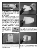
Page 8: ...to lightly wet the threads of the screws with threadlocker 3 Cut the nose wheel pushrod guide tube to a length of 14 1 2 370mm then insert it up through the fuselage where shown it may be necessary to trim the bottom of the fuel tank plate block to accommodate the tube Cut Off Threaded End Nose Steering Pushrod 17 1 2 445mm 90 4 Make a 17 1 2 445mm non threaded pushrod by cutting the threaded end ...

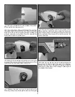
Page 9: ... envision the installation taking into consideration throttle pushrod location needle valve placement etc 1 Mount the motor mount to the firewall with M4 x 25 SHCS and M4 lock washers and flat washers but don t tighten the screws all the way yet 2 Adjust the mount to fit your engine then temporarily tighten the screws Position the engine so the spinner back plate will be 5 1 2 140 mm from the fire...

Page 10: ...el tank plate in the fuselage with the Velcro tank strap Fasten the tank plate with four M3 x 10 screws a 2 or 3 Phillips screwdriver works best on these screws HOOK UP THE THROTTLE INSTALL THE FUEL TANK 1 Although the fuel tank is assembled removing the stopper assembly and making a quick inspection to make sure the lines and clunks are secure is recommended After a quick look reinstall the stopp...

Page 11: ...you to spread the cowl apart for positioning over the engine If you re not using the 65AX you ll have to test fit and cut the cowl proceeding slowly and cutting in small increments for a good fit A No 569 and or 570 Dremel grout removal bit and a sanding drum are indispensable tools for accurately cutting a cowl Always wear eye and breathing protection when cutting fiberglass 1 For the 65AX cowl c...

Page 12: ...n then mark where the cowl needs more cutting to fit 7 Remove the cowl cut test fit mark and cut as necessary until you can at least get the cowl over the engine 8 Once you can get the cowl over the engine fit the spinner onto the crank shaft and see where the cowl needs more cutting to align eventually you ll need to cut the hole for the carburetor then finally cut for the little vertical rib on ...

Page 13: ...red for a perfect fit around the engine carburetor etc Mark the cowl where additional trimming is required Also cut holes for the muffler screws and attach the muffler cutting the cowl where necessary to accommodate these parts 15 Remove the cowl and trim as necessary Finally install the needle valve then mount the cowl The needle valve is close enough to the cowl that you can press on the cowl ov...

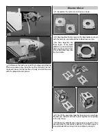
Page 14: ... back plate as shown with the holes to your left and the tabbed layer on top B Glue together the three layers of the front plate in any order all three parts are the same Press in four M4 blind nuts into the front plate C Test fit the assembly together to make sure everything fits and you understand how it goes together when gluing in the next step D Make any adjustments necessary for a good fit t...

Page 15: ...ng on bullet connectors and a battery connector then mount the ESC with 4 x 3 8 or M3 x 10 screws not included Connect the motor wires to the ESC NOTE If using a different ESC that does not fit on the motor mount box inside the cowl the ESC could be mounted in the fuselage behind the firewall but accommodations such as cutting cooling holes in the fuselage should be made for cooling the motor 4 Fo...

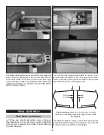
Page 16: ...y Temporarily connect the servos switch and battery to the receiver and power up the radio This will allow you to center the servos 2 Hook up the elevator and rudder as shown 1 16 1 6mm holes are drilled in the servo tray for the servo screws and 3 32 2 4mm holes are drilled in the elevator and rudder for the horn mounting screws 4 5 102mm 127mm The recommended C G is 4 5 102mm 127mm back from the...

Page 17: ...s trim any blocks necessary that interfere with the servos then glue the blocks into position 6 Place the radio mount plate into position on the blocks then drill 3 32 2 4mm holes into the blocks 7 Securely mount the receiver and Rx battery to the radio plate for quick removal of the battery for charging purposes we used adhesive back Velcro not included and a Velcro strap made from the included V...

Page 18: ...imbing PREFLIGHT ENGINE SAFETY PRECAUTIONS Failure to follow these safety precautions may result in severe injury to yourself and others Keep all engine fuel in a safe place away from high heat sparks or flames as fuel is very flammable Do not smoke near the engine or fuel and remember that engine exhaust gives off a great deal of deadly carbon monoxide Therefore do not run the engine in a closed ...

Page 19: ...r any reason always turn on the transmitter first before connecting the motor battery Also make certain your failsafe is programmed correctly so in the event the receiver ever loses signal or if you inadvertently turn off the transmitter before disconnecting the battery or vice versa the motor will not turn Follow the instructions that came with your radio control system to check and set the fails...

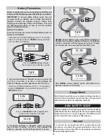
Page 20: ...are being joined in PARALLEL The result will be one 11 1V 3000mAh battery 2 Connecting batteries in Parallel means to connect the s to the s and the s to the s This combines the battery s capacities but the Voltage remains the same PARALLEL adapter 2 Cell 3 Cell 11 1V 7 4V PARALLEL ter 3 NEVER connect battery packs with different Voltages in Parallel only combine in Series Otherwise the batteries ...

Page 21: ...radio equipment ground check before the first flight of a new or repaired model 2 I will not fly my model aircraft in the presence of spectators until I become a qualified flier unless assisted by an experienced helper 3 At all flying sites a straight or curved line s must be established in front of which all flying takes place with the other side for spectators Only personnel involved with flying...

Page 22: ...le slower than contemporary aerobatic planes but is in alignment with pattern planes from that era The Kaos is a well balanced neutral easy flying plane that exhibits no bad tendencies and will go wherever you point it Simply fly the Kaos within your capabilities and take it easy for the first couple of flights to give yourself time to become acclimated to it Have a ball But always stay in control...

Page 23: ...23 NOTES ...

Page 24: ...TOWA2058 2015 Tower Hobbies A subsidiary of Hobbico Inc ...

Reviews: