


Chapter 2 — Getting Started
Installing the 2nd display (for Pro type only)
To
install
the
2
nd
display
onto
the
FS100
Terminal,
do
the
following:
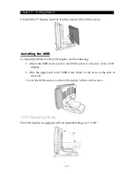
1.
Connect
the
DB
15
cable
to
the
connector
on
the
back
of
the
FS100
Terminal
LCD
screen
and
arrange
the
cable
in
the
clamp
as
shown.
DB 15
connector
Cable clamp
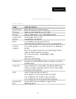
2.
Replace
the
base
cover.
Connect
one
end
of
the
DC
12V
adapter
cable
to
the
base
and
allow
the
other
end
of
the
cable
pass
through
the
hole
on
the
2
nd
Display
cover
stand.
DC 12V adapter
cable
Base
cover
2
nd
Display
cover stand
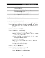
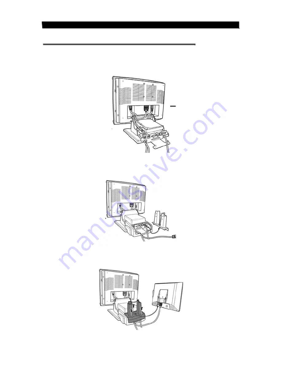
3.
Affix
the
2
nd
Display
cover
stand
to
the
base
with
three
M3
screws.
Next,
connect
the
other
end
of
the
DC
12V
adapter
cable
and
the
DB
15
cable
to
the
2
nd
Display.
11


