background image

18

Parts table

Parts

 Please make sure all the parts are prepared.

 Cross screwdriver is needed during the assembling.

Part's name  

Quantity

Wall bracket (right, left)

2

Metal connector

1

TV fix bracket

M8

M6

M4

M8

M6

M4

M8

M6

M4

M8

M6

M4

M8

M6

M8

M6

M4

M8

M6

M4

M8

M6

M4

M8

M6

M4

M8

M6

M4

M8

M6

M8

M6

M4

2

55WL800/55X1000C dedicated parts 

Quantity

Separate terminal enclosure 

(55/WL800, 55X1000C) 

Speaker bracket 

(55WL800/55X1000C) 

1 PS for 

each

55X2

Small parts putted inside the bag

Bag 

number

Part's name

Quantity

Screw (M8×75)

4

Pad (L=61mm)

4

Screw (M8×55)

4

Pad (L=41mm)

4

Screw (M8×40)

4

Pad (L=26mm)

4

Screw (M8×25)

4

Pad (L=11mm)

4

Screw (M8×14)

4

Nut M5x160

2

Screw (M5×8)

4

Screw (M5×8) 

1

Screw (M4×8)

2

● 

Meaning of crew type as follows.

[Example] M5×8
 

Length of the screw (mm)


Diameter of the screw (mm)

Dimension of the screw

L

t

φ

Flat washer

Spring 

washer

Screw type, Size of the parts

φ


L

M8 × 14, 25, 40, 55,75 Screw

M8

3.6

14,  25,  40,  55,  75

M6 × 14, 25, 40, 55, 75 Screw

M6

3.2

14,  25,  40,  55,  75

M5 × 8, 25, 40, 55, 75 Screw

M5

2.3

8

M4×8 Screw

M4

1.8

8

Specification

Model: WAL14C
Dimension:  (W) 

268mm (about distance at 200mm), 420mm (spacer)


468mm (about distance at 400mm)


(D)  

27mm (Wall bracket)


(H) 

526mm

Weight:  

  Metal mounting bracket only: 2.5kg; Metal mounting bracket and pad: Maximum 2.7kg

Adjustable angle: 0°,  5°,  10°,  15°

Design and specification are subject to change without notice.

C100047_WAL14C_EN.indd   18

2010/12/15   13:34:19

Summary of Contents for WAL14C

Page 1: ...1 VX1A00189800 Model Operation Manual For LCD Color TV Toshiba Wall Mounting WAL14C C100047_WAL14C_EN indd 1 2010 12 15 13 33 59 ...

Page 2: ...s at least Please make sure no screw or part disassembled is missed Please consult thoroughly with the user before the application and start the operation upon the agreement of the user Once the application is finished please check and make sure it has been installed safely and correctly and then hand this operation manual of wall mounting to the user 1 About the wall structure and material to fix...

Page 3: ...rohibited action Do not do The action prohibited is described within or near the symbol by diagram or words Direction indicates a required action Do The action required is described within or near the symbol by diagram or words Exemptions Toshiba is not liable for any damage caused by natural disaster such as fire earthquake by the act of the third person accidents owner s intentional acts neglige...

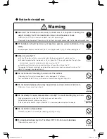
Page 4: ...n on it Otherwise it may fall overturn or be damaged resulting in injury The family with children in particular should pay full attention to it Prohibition Do not hang or place anything on wall mounting or TV Otherwise the object placed or the TV may fall and cause death or injury Disassembly prohibited Do not attempt to repair disassemble or modify the wall mounting on your own Otherwise the wall...

Page 5: ...id the strike to the TV The neglect of these instructions may break the electric wire and may cause fire shock fall down TV damage even lead to injury Prohibition Do not fix the wall mounting to a wall out of the vertical Otherwise the TV may fall cause death injury damage of TV or floor And ventilation of the TV may turn worse cause inner heating resulting in fire Splash prohibited Do not install...

Page 6: ... the weight for a long duration and then hand this operation manual to the user Improper installation may cause fall of the TV leading to death injury TV or floor damage etc 警告 Caution Prohibition Do not block the LCD color TV ventilation holes on the top of the screen If these holes are blocked heat will gather inside the TV causing a fire Leave a space of about 10cm around the equipment body Do ...

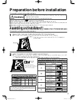
Page 7: ...ng screws and pads will be different depending on the installation angle size of the TV screen the installation direction and shape of the terminals 1 Please refer to the table at the lift side when selecting the proper combination of the small components Spacer Peel off the protection of double sided adhesive paper fix the spacer to the screw at the still bracket of the TV set body Protection pap...

Page 8: ...rea of 80mm2 located under TV set side steel mounting bracket The contact between prohibited areas of connection and Wall bracket or TV fix bracket caused by hanging may lead to damage of the connection or installation failure of the TV Assembling and Installation 2 when installing the speaker to the host of the TV monitor 1 Preparation of the dedicated speaker for the LCD monitor host Take the LC...

Page 9: ...e supplied 4 screws and spacer The combination of the screws and pads depends on the installation angle and screen size Please store the removed stand and other components carefully 1 Install the right spacers provided Fixed screws Spacer Peel off the protection of double sided adhesive paper fix the spacer to the screw at the still bracket of the TV set body Protection paper The attachment combin...

Page 10: ...d so forth Install the specific speaker bracket to match with the model 55X2 Speaker bracket Screws for installation M5 8 Screws for installation M4 8 Use the fixed screws M5 8 PS1 M4 8 2PS inside the provided bag Ⓖ to install speaker bracket to the display 3 Gather the connections together and get them through the cable clips speaker bracket and install the separate terminal enclosure to the spea...

Page 11: ...n the level Model About distance Screw holes for metal connector 46 55WL700E T 55WL800E T V 400mm Outer screw hole 55X1000C 400mm Outer screw hole 400mm When the about distance is 400mm between screws of the metal mounting bracket at the back of the TV set Left side of the label Fixed screws M5 8 Right side of the label Maintain the level Maintain the level Metal connector 200mm When the about dis...

Page 12: ... bolts or screws Market available mounting bolts or screws Screw hole at Φ8 6 Screw hole at Φ13 6 Fixed screws Angle adjustment span Installation points using expansion screws 10mm of the expansion screw threads shall be left out side of the wall when it is embedded in the wall Secure the wall bracket to the expansion screws and be sure a maximum of 15mm distance is allowed from the screw tip to t...

Page 13: ...brackets at the both sides by same method Please make sure that the installation angle of the TV shall keep correspondence with the installed spacer The lower part of the TV back will press against to the wall if the spacer is improperly used 0 15 10 5 You do not use it At 15 At 10 At 5 State of side metal brackets on the wall after angle adjustment Angle adjustment Fixed screws Fixed screws Angle...

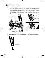
Page 14: ...d angle adjustment portion slowly Insert the lower long screw hanging part of the TV fix bracket to long fixed screws for the TV set body Wall bracket Angle adjustment part Lower long screw hanging part of the TV fix bracket Protruding hanging slot on the TV fix bracket Protruding hanging slot on the TV fix bracket Protruded angle adjustment portion Protruded angle adjustment portion Lower long sc...

Page 15: ...ep 4 14 in Assembling installation Change and extension of connections If the extension and change of the connection is required after the installation please consult the dealer or ask the qualified technicians to do it Please remove the TV from the wall mounting before extending or changing the connections The operation must be done by more than 2 people Extension and change of connection of the ...

Page 16: ...quipment Please take full care during the operation to avoid damage of wire etc 3 Loose the fixed screws of the wall mounting 4 Disassembly in accordance with the following steps Lift the LCD TV slightly and release the TV fix brackets from the lower long screw hanging part Release the protruding hanging slot on the TV fix bracket from protruded angle adjustment portion Take the TV set off with an...

Page 17: ... 4 φ8 16 16 16 99 198 115 526 16 25 4 φ13 200 268 68 420 46 46 68 246 4 φ8 16 16 16 99 198 115 526 16 25 4 φ13 Ⓑ Ⓔ Ⓒ Ⓓ 466 5 Ⓐ Ⓗ 466 5 Ⓘ Ⓕ Ⓖ 15 Spacer Model Ⓐ Ⓑ Ⓒ Ⓓ Ⓔ Ⓕ Ⓖ Ⓗ Ⓘ Minimum Maximum Minimum Maximum 46WL700 224 56 82 98 98 27 53 53 27 64 110 55WL700 238 56 82 153 153 27 53 38 13 115 163 55WL800 291 88 138 149 234 38 88 58 12 98 258 55X1000C 291 88 138 149 234 38 88 58 12 98 258 Maximum and...

Page 18: ... 4 Ⓓ Screw M8 25 4 Pad L 11mm 4 Ⓔ Screw M8 14 4 Ⓕ Nut M5x160 2 Screw M5 8 4 Ⓖ Screw M5 8 1 Screw M4 8 2 Meaning of crew type as follows Example M5 8 Length of the screw mm Diameter of the screw mm Dimension of the screw L t φ Flat washer Spring washer Screw type Size of the parts φ t L M8 14 25 40 55 75 Screw M8 3 6 14 25 40 55 75 M6 14 25 40 55 75 Screw M6 3 2 14 25 40 55 75 M5 8 25 40 55 75 Scre...

Reviews: