background image


T1000 Series UPS 1000-3000VA Installation and Operation Manual 

– 94086-001 

1  GENERAL SAFETY INSTRUCTIONS 

DO  NOT

 attempt to install,  operate, maintain or dispose of this equipment until you  have 

read and understood all of the product safety information and directions that are contained 
in this manual. 

Safety Alert Symbol


The 

Safety  Alert  Symbol

  indicates  that  a  potential  personal  injury  hazard  exists.  The 

symbol is comprised of an equilateral triangle enclosing an exclamation mark. 


Signal Words


Listed  below  are  the  signal  words  that  are  used  throughout  this  manual  followed  by  their 

descriptions  and  associated  symbols.  When  the  words 

DANGER

WARNING

  and 

CAUTION

  are  used  in  this  manual  they  will  be  followed  by  important  safety  information 

that must be carefully adhered to. 


The  word 

DANGER

  preceded  by  the  safety  alert  symbol  indicates  that  an  imminently 

hazardous  situation  exists  that,  if  not  avoided,  will  result  in  death  or  serious  injury  to 

personnel. 


DANGER


Summary of Contents for T1000 Series

Page 1: ...ERRUPTIBLE POWER SYSTEM UPS T1000 SERIES Installation and Operation Manual Single Phase 1000 3000VA Part Number 94086 001 Date March 2018 Copyright 2018 TOSHIBA International Corporation All rights reserved ...

Page 2: ......

Page 3: ...ariations in equipment or to provide for every possible contingency concerning installation operation or maintenance Should further information be required or if problems arise which are not covered sufficiently contact your Toshiba sales office The contents of this instruction manual shall not become a part of or modify any prior or existing agreement commitment or relationship The sales contract...

Page 4: ...T1000 Series UPS 1000 3000VA Installation and Operation Manual 94086 001 ii ...

Page 5: ...see Toshiba International Corporation bill of lading Please complete the following information and retain for your records Job Number _____________________________________________________________ Model Number ___________________________________________________________ Serial Number ___________________________________________________________ Application _____________________________________________...

Page 6: ...n metric and or the English customary equivalent Toshiba International Corporation reserves the right without prior notice to update information make product changes or discontinue any product or service identified in this publication Toshiba is a registered trademark of the Toshiba Corporation All other product or trade references appearing in this manual are registered trademarks of their respec...

Page 7: ...nformation Customer Support Center 8 a m to 5 p m CST Monday through Friday USA Toll Free 877 867 8773 Field Service Tech Support USA Toll Free 855 803 7087 Pre sales Application Support You may also contact Toshiba International Corporation by writing to Toshiba International Corporation Power Electronics Division UPS 13131 West Little York Road Houston Texas 77041 9990 Attn T1000 UPS Product Man...

Page 8: ...IPTION 11 6 1 GENERAL DESCRIPTION 12 6 2 SYSTEM CONFIGURATION 13 7 SAFETY INFORMATION 14 8 INSTALLATION 14 9 INSPECTION STORAGE DISPOSAL 15 10 INSTALLATION PRECAUTIONS 17 11 OPERATING PRECAUTIONS 18 12 INSTALLATION 19 12 1 ENVIRONMENT 19 12 2 REAR PANEL VIEW 20 12 3 CONNECTION TO MAINS AND LOADS 1000VA TO 3000VA 26 12 4 CONNECTION TO MATCHING EXTERNAL BATTERY CABINET27 13 COMPUTER AND ALARM CONNEC...

Page 9: ...G BATTERIES 38 16 TECHNICAL SPECIFICATIONS 39 16 1 POWER RANGE 1000VA 3000VA 120V MODEL 39 16 2 POWER RANGE 1000VA 3000VA 230V MODEL 40 16 3 ENVIRONMENTAL AND STANDARDS 1000VA 3000VA 41 16 4 OUTPUT POWER 120V TOWER MODELS 41 16 5 OUTPUT POWER 120V RACKMOUNT MODELS 41 16 6 OUTPUT POWER 230V TOWER MODELS 42 16 7 OUTPUT POWER 230V RACKMOUNT MODELS 42 16 8 COMMUNICATIONS 42 16 9 PHYSICAL 43 16 10 WARR...

Page 10: ... 20 Figure 3 2000VA Tower Rear Panel View 21 Figure 4 3000VA Tower Rear Panel View 22 Figure 5 1000VA 1500VA Rackmount Rear Panel View 23 Figure 6 2000VA Rackmount Rear Panel View 24 Figure 7 3000VA Rackmount Rear Panel View 25 Figure 8 Example of Installation of Plug Play Product 26 Figure 9 Connecting External Battery Cabinet 27 Figure 10 Control Panel Layout 31 ...

Page 11: ...injury hazard exists The symbol is comprised of an equilateral triangle enclosing an exclamation mark Signal Words Listed below are the signal words that are used throughout this manual followed by their descriptions and associated symbols When the words DANGER WARNING and CAUTION are used in this manual they will be followed by important safety information that must be carefully adhered to The wo...

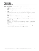
Page 12: ...jury The word CAUTION in capital letters without the safety alert symbol indicates that a potentially hazardous situation exists which if not avoided may result in equipment or property damage Special Symbols To identify special hazards other symbols may appear in conjunction with the DANGER WARNING and CAUTION signal words These symbols indicate areas that require special and or strict adherence ...

Page 13: ...ning Labels DO NOT attempt to install operate maintain or dispose of this equipment until you have read and understood all of the product warnings and user directions that are contained in this instruction manual Labels attached to the equipment are there to provide useful information or to indicate an imminently hazardous situation that may result in serious injury severe property and equipment d...

Page 14: ...nants Make sure air vents on the UPS are not blocked Allow adequate space for proper ventilation The equipment is heavy Always practice safe lifting procedures adequate for the weight of the equipment Install battery modules cabinets at the bottom in rackmount configurations The UPS is to be installed above the battery modules cabinets Battery servicing should be performed by a qualified Toshiba R...

Page 15: ...f this equipment could result in injury and equipment damage In no event will Toshiba Corporation be responsible or liable for either indirect or consequential damage or injury that may result from the misuse of this equipment Do not dispose of the batteries in a fire The batteries may explode Do not open or mutilate the batteries Released electrolyte is harmful to the eyes and skin and could also...

Page 16: ...gloves and boots 5 Do not place tools or any metal parts on top of batteries 6 Remove battery grounds during installation maintenance to reduce likelihood of shock Determine if the battery is inadvertently grounded If inadvertently grounded remove source of ground 7 Disconnect charging source prior to connecting or disconnecting battery terminals Contact with any part of a grounded battery can res...

Page 17: ...r service to qualified service personnel Non isolated battery supply Risk of electric shock battery circuit is not isolated from AC input Hazardous voltage may exist between battery terminals and ground Test before touching When replacing batteries replace with the same type and number of batteries One Sealed lead acid battery rated 12V 9 AH max To reduce risk of fire use only No 26 AWG or larger ...

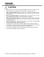
Page 18: ... installation and follow up maintenance of the UPS and batteries CAUTION The unit has a dangerous amount of voltage If the UPS indicator is on the unit s outlets may have a dangerous amount of voltage even when not plugged into the wall outlet because the battery may continue to supply power Ensure installation is indoors free from electrically conductive particles temperature and humidity control...

Page 19: ...al for additional information such as important operating and maintenance instructions SAFE GROUNDING TERMINAL Indicates primary safe ground LOAD ON OFF Pressing this button turns on off the output receptacles and the Indicator light RJ 45 RECEPTACLE The receptacle provides network interface connections and telephone or telecommunications equipment should not be plugged into it Please do not disca...

Page 20: ... occur in some installations If by turning on and off it can be deduced that your radio or television reception is found to be influenced by harmful interference from the equipment it is recommended to use one of the following preventive measures Place the receiving antenna in a separate location or orientation Ensure a greater distance is achieved between the receiver and the equipment Ensure tha...

Page 21: ...ed by a UPS Uninterruptible Power System including computers workstations process control systems telecommunications systems sales terminals other critical instrumentation etc The purpose of the UPS is to protect these systems from poor quality utility power complete loss of power or other associated problems Electrical interference abounds in many forms causing problems in AC power from lightning...

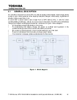
Page 22: ...will shut down avoiding battery discharge and as soon as power comes back the UPS will automatically charge up and start recharging the batteries As shown in Figure 1 block diagram An input filter reduces transients on the mains For maintaining full battery charge AC power is rectified and regulated in the rectifier feeding power to the inverter and battery converter DC power is converted to AC in...

Page 23: ...Hz 0 25Hz Please refer to section 13 if you want bypass available while running in free run mode Diagnostic tests When you start the UPS a diagnostic test is automatically executed that checks electronics battery and reports any problems on the LCD display An advanced battery management system always monitors the conditions of the batteries sends any fore warnings if replacement is needed Otherwis...

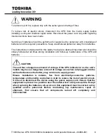
Page 24: ...fely Not acknowledging such electrical hazards may be fatal so keep this manual for all future reference WARNING It is strongly advisable not to open the UPS cabinet as the components have very high voltage and touching them may be fatal Only a technician from the manufacturer or an authorized agent may service the unit This UPS unit s output receptacles carry live voltage even when not connected ...

Page 25: ...he instructions in section 13 6 4 Ensure all switches are in the Off position Storing Conditions For best results store the UPS in the original shipping container and place on a wood or metal pallet Storage temperature 5 122 F 15 to 50 C The recommended storage temperature is 59 to 77 F 15 to 25 C A higher ambient temperature will require recharging the batteries more frequently during storage Avo...

Page 26: ...tallation and Operation Manual 94086 001 16 Please help our Earth by contacting the environmental protection agencies in your area the battery manufacturer or call Toshiba toll free at 877 867 8773 for more information about recycling ...

Page 27: ...d inside of the unit there is no guarantee that the UPS will not influence some sensitive devices that are operating nearby If such interference is experienced the UPS should be installed farther away from the affected equipment and or powered from a different source than that of the affected equipment 10 The user should provide output over current protection for hardwired UPS systems 11 After ens...

Page 28: ... UPS model is provided via a cabinet label and a CHARGE LED Wait for at least the minimum time indicated on the label and ensure that the CHARGE LED has gone out before opening the door of the UPS once the UPS power has been turned off 8 Do not attempt to disassemble modify or repair the UPS Call your Toshiba sales representative for repair information 9 Turn the power on only after attaching ALL ...

Page 29: ...ments are met according to these technical specifications otherwise the safety of installation personnel cannot be guaranteed and the unit may malfunction Follow below instructions when locating the UPS system and battery options Avoid extreme temperature and humidity Maximal battery life can be attained with a recommended temperature range of 15 C to 25 C Protect the equipment from moisture Space...

Page 30: ...s UPS 1000 3000VA Installation and Operation Manual 94086 001 20 12 2 REAR PANEL VIEW 1000VA 1500VA Tower Rear Panel Figure 2 1000VA 1500VA Tower Rear Panel View T1S0A1000AXA T1S0A1500AXA T1S0A1000FXF T1S0A1500FXF ...

Page 31: ...T1000 Series UPS 1000 3000VA Installation and Operation Manual 94086 001 21 2000VA Tower Rear Panel Figure 3 2000VA Tower Rear Panel View T1S0A2000FXF T1S0A2000AXA ...

Page 32: ...T1000 Series UPS 1000 3000VA Installation and Operation Manual 94086 001 22 3000VA Tower Rear Panel Figure 4 3000VA Tower Rear Panel View T1S0A3000AXA T1S0A3000FXF ...

Page 33: ...es UPS 1000 3000VA Installation and Operation Manual 94086 001 23 Rackmount 2U 1000VA 1500VA Rear Panel Figure 5 1000VA 1500VA Rackmount Rear Panel View T1S0A1000AXAR2 T1S0A1500AXAR2 T1S0A1000FXFR2 T1S0A1500FXFR2 ...

Page 34: ...T1000 Series UPS 1000 3000VA Installation and Operation Manual 94086 001 24 Rackmount 2U 2000VA Rear Panel Figure 6 2000VA Rackmount Rear Panel View T1S0A2000AXAR2 T1S0A2000FXFR2 T1S0A2000AXAR2P1 ...

Page 35: ...T1000 Series UPS 1000 3000VA Installation and Operation Manual 94086 001 25 Rackmount 2U 3000VA Rear Panel Figure 7 3000VA Rackmount Rear Panel View T1S0A3000AXAR2 T1S0A3000AXAR2P1 T1S0A3000FXFR2 ...

Page 36: ...er end to a grounded outlet The batteries will automatically charge when connected to the mains Please realize that although you may start using the UPS immediately maximum back up time will still not be available so it is recommended to charge the batteries for a minimum of 8 hours before use If unit instantly shows a Site Wiring Fault rotate the connector see Section 13 5 After charging the UPS ...

Page 37: ...is disconnected from mains and loads while connecting the External Battery Cabinet Use the battery cable that comes with the External Battery Cabinet to connect the External Battery Cabinet to the UPS Connect a second battery cabinet to the first one with the cable provided if more than one is to be installed This UPS may be provided with maximum two extension battery cabinets Figure 9 Connecting ...

Page 38: ...kage with power management software Only the communication cable provided with UPS may be used to connect to your computer which is accomplished through the UPS RS232 port Also ensure that the operating system on your computer is supported Instructions provided in the power management software will help with this installation RS 232 Standard Interface port not for remote dry contact purpose The RS...

Page 39: ...t protector located on the back panel has both IN and OUT jacks and houses a single RJ 45 10BaseT network connector Connect the input connector to the jack labeled IN and the output connector to the jack labeled OUT 13 2 LOAD SEGMENTS 1000VA TO 3000VA The power management software controls the sets of receptacles known as load segment which provides organized shutdown and startup of the equipment ...

Page 40: ...en output power has commenced and the LCD will display Line mode Switch on the loads Shut down the UPS Shut down and turn off all the loads Press and hold the button on the front panel for five seconds The alarm will sound and the UPS will shut down The LCD will display UPS OFF for a few seconds In emergency situations the EPO located on the back of the unit should be used 14 2 BUTTON OPERATION Pl...

Page 41: ...EL FUNCTIONS Operation of the UPS is indicated on the monitor panel with five LED indicators and an LCD screen This display is also capable of alerting the user with audible alarms ON This green LED is lit when UPS has been turned on ON LINE When the UPS is in normal or static bypass modes there is voltage at the output terminals and this LED will light up in green ON BAT While operating in batter...

Page 42: ...y TEMPERATURE xxC Shows approximate ambient temperature BAT PACK NUM x Shows External Battery Pack Number RATING xxxxVA Shows UPS Rating CPU VERSION xx x Shows CPU Version UPS Configurations Various settings that have been chosen are shown in the UPS setting display To enter configuration mode press and hold the button for one second The first configuration parameter will be shown on the LCD displ...

Page 43: ... UPS can go to bypass when unsynchronized Disable Enable Disable He mode Setting HE Mode Set Select if UPS runs in high efficiency mode ON OFF OFF Force Manual Bypass Manual bypass Permanently force UPS to bypass For service only ON OFF OFF Management of Load groups Outlet Setting You can put the two load groups on and off form front panel 1 ON 2 ON 1 OFF 2 ON 1OFF 2 OFF 1 ON 2 OFF Both load segme...

Page 44: ...enance bypass switch Note You should turn UPS off and keep the AC power before you use Generator function Even you want to select Generator OFF to back to normal mode 14 4 INTERPRETING UPS MESSAGES Troubleshooting procedures described here give simple instructions in determining UPS malfunctions Start the troubleshooting procedure if you witness any alarm indication on the control panel Alarm indi...

Page 45: ...on due to very low battery voltage The unit will restart Automatically when acceptable power returns On Battery 1 beep every 5 seconds The unit is operating on Battery Power Save your data and perform a controlled shutdown Charger Failure Constant beep Charger has failed Call Service Over Temperature No Beeps High ambient Temperature Make sure the unit s fans and vent holes are not blocked and mak...

Page 46: ...e backed up during auto restart 14 6 COLD START DISABLE PROCEDURE a Ensure the UPS is switched OFF b Plug In AC Power c Press and hold the Function Key while pressing the Enter key 3 times d After a beep sounds unplug the AC power cord and wait for UPS to shutdown automatically Note Cold start will be automatically re enabled when the UPS is plugged into commercial power and switched ON ...

Page 47: ...ut is affected by the environment and usage in backup mode Check the back up battery at regular intervals of 6 to 12 months to determine whether the back up time of the battery is adequate for its intended purpose WARNING Batteries may cause electrical shock or burns from high short circuit currents Please observe the following precautions 1 Remove jewelry and metal objects such as watches and rin...

Page 48: ...1000 3000 VA The following is a step by step tutorial for replacing the batteries 1 The front panel of the UPS can be removed by pushing where the arrows indicate in the pictures above Next unscrew the screws and remove the metal battery cover 2 Remove the battery cartridge from the UPS The voltage in all models will be less than 48Vdc once the battery is disconnected from the UPS 3 Replace the ba...

Page 49: ...er factor 0 97 Rated Input Current 12 0A 12 0A 16 0A 24 0A OUTPUT Output Power Factor 0 9 Nominal Output Voltage 120V Other Output Voltage 100 110 115V selectable from LCD panel Voltage regulation 2 Voltage distortion 5 THD at full non linear load 2 5 THD at full linear load Rated Current 120 VAC 8 3A 13 7A 16 6A 25 0A Output Frequency 50 60 Hz 5 Frequency regulation 0 25 Hz battery or free runnin...

Page 50: ... Rated Input Current 4 7A 7 0A 9 4A 14 1A OUTPUT Output Power Factor 0 9 Nominal Output Voltage 230V Other Output Voltage 208 220 240V selectable from LCD panel Voltage regulation 2 Voltage distortion 5 THD at full non linear load 2 5 THD at full linear load Rated Current 230 VAC 4 3A 6 5A 8 7A 13A Output Frequency 50 60 Hz 5 Frequency regulation 0 25 Hz battery or free running mode Wave Form Type...

Page 51: ... 5 15R x 6 5 20R x 12 5 20R x 8 L5 30R x 1 Battery type Lead acid 9AH 12V FR Number of batteries 3 4 6 8 Est Backup time full load 5 min Recharge time 4 hours to over 90 Dimensions WxDxH in 6 0 x 16 5 x 9 4 6 0 x 19 7 x 9 4 8 9 x 16 5 x 14 1 Net Weight 33 4 lbs 42 7 lbs 67 1 lbs 68 4 lbs 16 5 OUTPUT POWER 120V RACKMOUNT MODELS OUTPUT POWER 1000VA 1500VA 2000VA 3000VA Connection Input 5 15P 5 20P L...

Page 52: ...9 7 x 9 4 8 9 x 16 5 x 14 1 Net Weight 33 4 lbs 42 7 lbs 63 4 lbs 66 lbs 16 7 OUTPUT POWER 230V RACKMOUNT MODELS OUTPUT POWER 1000VA 1500VA 2000VA 3000VA Connection Input IEC 320 C14 Schuko CEE 7 IEC 320 C20 Schuko CEE 7 Connection Output IEC 320 C13 x 4 IEC 320 C13 x 4 IEC 320 C19 x 1 Battery type Lead acid 9AH 12V FR Number of batteries 3 4 6 Est Backup time full load 5 min 3 min Recharge time 4...

Page 53: ...2 4 lbs Color Black RACKMOUNT 1000VA 1500VA 2000VA 3000VA Unit Dimensions in 16 9 16 7 3 3 16 9 x 19 7 x 3 3 16 9 25 3 3 Shipping Dims in 21 4 x 21 7 x 8 1 21 4 x 24 x 8 1 21 7 x 29 5 x 8 7 Net Weight lbs 35 9 lbs 39 4 lbs 65 1 lbs 73 9 lbs Shipping Weight lbs 42 7 lbs 46 2 lbs 74 6 lbs 80 3 lbs Color Black 16 10 WARRANTY Standard Warranty 3 years excluding battery and 2 years for battery See Tosh...

Page 54: ...NANT LA SÉCURITÉ CONSERVER CES INSTRUCTIONS Cette notice contient des instructions importantes concernant la sécurité Une battery peut présenter un risque de choc électrique de brûlure par transfert d énergie L ÉLIMINATION DES BATTERIES EST RÈGLEMENTÈE CONSULTER LES CODES LOCAUX À CET EFFET ATTENTION ATTENTION ...

Page 55: ...ontres bagues et tout objet métallique B Utiliser des outils à poignée isolée C Porter des gants et des bottes en caoutchouc D Éviter de déposer des outils ou des pièces métalliques sur le dessus de la batterie E Débrancher la source de charge avant de brancher ou de débrancher les bornes de batterie ATTENTION Ne convient pas aux utilisations dans une salle d ordinateurs tel que spécifié par la no...

Page 56: ...13131 West Little York Rd Houston TX 77041 Tel 713 466 0277 Fax 713 466 8773 US 877 867 8773 www toshibaups com Printed in Taiwan ...

Reviews: