– 24 –
9. OPERATION DESCRIPTION
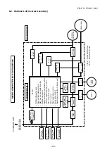
9-1. Outline of Air Conditioner Control
This air conditioner is a capacity-variable type air
conditioner, which uses AC or DC motor for the indoor
for motor and the outdoor fan motor. And the capacity-
proportional control compressor which can change the
motor speed in the range from 11 to 96 rps is
mounted. The DC motor drive circuit is mounted to the
indoor unit. The compressor and the inverter to control
fan motor are mounted to the outdoor unit.
The entire air conditioner is mainly controlled by the
indoor unit controller.
The indoor unit controller drives the indoor fan motor
based upon command sent from the remote controller,
and transfers the operation command to the outdoor
unit controller.
The outdoor unit controller receives operation com-
mand from the indoor unit side, and controls the
outdoor fan and the pulse Modulating valve. (P.M.V)
Besides, detecting revolution position of the compres-
sor motor, the outdoor unit controller controls speed of
the compressor motor by controlling output voltage of
the inverter and switching timing of the supply power
(current transfer timing) so that motors drive according
to the operation command.
And then, the outdoor unit controller transfers reversely
the operating status information of the outdoor unit to
control the indoor unit controller.
As the compressor adopts four-pole brushless
DC motor, the frequency of the supply power
from inverter to compressor is two-times cycles
of the actual number of revolution.
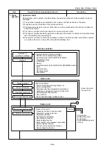
1. Role of indoor unit controller
The indoor unit controller judges the operation
commands from the remote controller and assumes
the following functions.
• Judgment of suction air temperature of the indoor
heat exchanger by using the indoor temp. sensor.
(TA sensor)
• Judgment of the indoor heat exchanger tempera-
ture by using heat exchanger sensor (TC sensor)
(Prevent-freezing control, etc.)
• Louver motor control
• Indoor fan motor operation control
• LED (Light Emitting Diode) display control
• Transferring of operation command signal (Serial
signal) to the outdoor unit
• Reception of information of operation status
(Serial signal including outside temp. data) to the
outdoor unit and judgment/display of error
• Air purifier operation control
2. Role of outdoor unit controller
Receiving the operation command signal (Serial
signal) from the indoor unit controller, the outdoor
unit performs its role.
• Compressor operation control
• Operation control of outdoor fan motor
• P.M.V. control
• 4-way valve control
Operations followed to judgment
of serial signal from indoor side.
• Detection of inverter input current and current
release operation
• Over-current detection and prevention operation
to IGBT module (Compressor stop function)
• Compressor and outdoor fan stop function when
serial signal is off (when the serial signal does not
reach the board assembly of outdoor control by
trouble of the signal system)
• Transferring of operation information (Serial
signal) from outdoor unit controller to indoor unit
controller
• Detection of outdoor temperature and operation
revolution control
• Defrost control in heating operation (Temp.
measurement by outdoor heat exchanger and
control for 4-way valve and outdoor fan)
3. Contents of operation command signal
(Serial signal) from indoor unit controller to
outdoor unit controller
The following three types of signals are sent from
the indoor unit controller.
• Operation mode set on the remote controller
• Compressor revolution command signal defined
by indoor temperature and set temperature
(Correction along with variation of room tempera-
ture and correction of indoor heat exchanger
temperature are added.)
• Temperature of indoor heat exchanger
• For these signals ([Operation mode] and [Com-
pressor revolution] indoor heat exchanger tem-
perature), the outdoor unit controller monitors the
input current to the inverter, and performs the
followed operation within the range that current
does not exceed the allowable value.
4. Contents of operation command signal
(Serial signal) from outdoor unit controller
to indoor unit controller
The following signals are sent from the outdoor unit
controller.
• The current operation mode
• The current compressor revolution
• Outdoor temperature
• Existence of protective circuit operation
For transferring of these signals, the indoor unit
controller monitors the contents of signals, and
judges existence of trouble occurrence.
Contents of judgment are described below.
• Whether distinction of the current operation
status meets to the operation command signal
• Whether protective circuit operates
When no signal is received from the outdoor
unit controller, it is assumed as a trouble.
FILE NO. SVM-13092

