8
REAR PANEL CONNECTORS
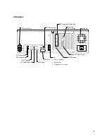
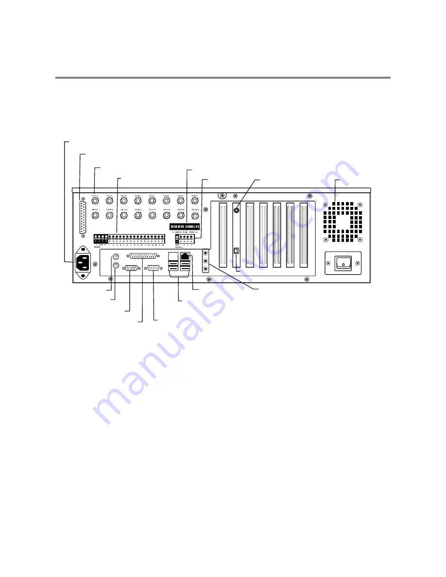
The rear panel of the XVR unit contains the connectors used to attach cameras, sensors, and relays to the XVR. Below are diagrams
that outline the location and description of each connector:
16 Channel
BNC Connectors for Video Input
Cooling Fan
AC Power Connector
Looping Output Termination
SVGA Output
Audio
•
Line In – line level
•
Speaker Out
•
Microphone In – not used
Sensors Inputs
LPT Parallel Printer Port
PS/2 Mouse Input
PS/2 Keyboard Input
DB-9 Serial Input
Adapter for BNC Looping Output Cable
USB Ports
Control Outputs
Network Port
RCA Video Out
RS-422 Interface
Summary of Contents for Surveillix XVR16-120-X
Page 9: ...ix ...
Page 10: ...x ...
Page 15: ...xv NOTES ...
Page 16: ...xvi NOTES ...
Page 20: ...4 NOTES ...
Page 26: ...10 NOTES ...
Page 38: ...22 NOTES ...
Page 39: ...23 ...
Page 40: ...24 ...
Page 47: ...31 ...
Page 48: ...32 ...
Page 77: ...61 NOTES ...
Page 78: ...62 ...
Page 89: ...73 NOTES ...
Page 90: ...74 NOTES ...
Page 98: ...82 NOTES ...
Page 104: ...88 NOTES ...
Page 107: ...91 NOTES ...
Page 108: ...92 NOTES ...
Page 109: ...93 EVENT SENTRY This chapter includes the following information Overview Setup Event Sentry ...
Page 112: ...96 NOTES ...
Page 116: ...100 NOTES ...
Page 129: ...113 APPENDIX SPECIFICATIONS ...
Page 130: ...114 ...


