background image


36


No Sequencing though 0 FPS Cameras 


Does not sequence through cameras that have 0 FPS specified. 


 Audio 

– Opens the Audio ENABLE/DISABLE options. 


TV Out Setup 

– Opens the TV Out setup options. 


Volume 

– Opens the Volume controls that affect the Audio Recording levels. 


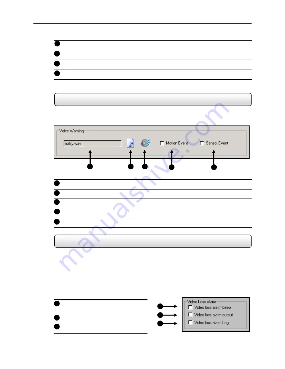
4.7.1 Voice 

Warning   

 
The DVR unit allows you to play a sound file when either a Motion event or Sensor event occurs. This file can be a 
custom created sound file that is unique to your application. The selected WAV file is played through speakers attached 
to the DVR unit.  


Display File to Use 

– Displays the Audio file that will be used during the Voice Warning Event. 


 Open 

– Allows you to select the location of the WAV file to use. Note – Only WAV files are supported.  


Play Selected WAV 

– Plays the selected WAV file. 


 Motion 

Event 

– Enables the Voice Warning on Motion Events. 


 Sensor 

Event 

– Enables the Voice Warning on Sensor Events


4.7.2 Video 

Loss 

Alarm 

 
The DVR supports a Video Loss Alarm function which allows an Alarm Event to occur when a camera loses signal. The 
lost signal can be due to Power failure to the camera, the camera cable being cut or unplugged, or the camera being 
damaged in some way.  
 
In order to use Video Signal Loss detection, cameras must either be turned ‘ON’ or ‘OFF’. This is because the DVR 
needs to know which cameras it should expect to receive signals from. To turn camera(s) ‘ON’, open FRAME SETUP, 
and set the Frames Per Second to anything above zero. By designating zero frames per second you are essentially 
saying that the camera is not going to be used by the DVR. 


Video Loss Alarm Beep 

– When Video Loss 

occurs an internal speaker on the DVR will 
sound an alarm. 


Video Loss Alarm Output 

– When Video Loss 

occurs, the Alarm Output is activated. 


Video Loss Alarm Log 

– Records the Video 

Loss Alarm events to the Log Files.  

Figure 4.7.1


Figure 4.7.1


Figure 4.7.2


Figure 4.7.2


12 


13 


14 


11 

Summary of Contents for surveillix KV-PCDVR

Page 1: ...Operations Manual Operations Manual KV PCDVR TM 8GHO44 88 ...

Page 2: ...ii ...

Page 3: ...S BUSINESS INTERRUPTION OR LOSS OF BUSINESS INFORMATION EVEN IF TOSHIBA HAS BEEN ADVISED OF THE POSSIBILITY OF SUCH DAMAGES AND WHETHER IN AN ACTION OR CONTRACT OR TORT INCLUDING NEGLIGENCE This software and documentation are copyrighted All other rights including ownership of the software are reserved to DVR Support Center TOSHIBA and Surveillix are registered trademarks of TOSHIBA CORPORATION in...

Page 4: ...tain the bill of sale or provide other proof of purchase 2 You must schedule service within thirty days after you discover a defective product or part 3 All warranty servicing of this product must be made by an ISD authorized service center 4 The warranty extends to defects in material or workmanship as limited above and not to any products or parts that have been lost or discarded by user The war...

Page 5: ... DANGEROUS HIGH VOLTAGES ARE PRESENT INSIDE THE ENCLOSURE DO NOT OPEN THE CABINET REFER SERVICING TO QUALIFIED PERSONNEL ONLY WARNING RISK OF ELECTRICAL SHOCK DO NOT OPEN WARNING TO REDUCE THE RISK OF ELECTRICAL SHOCK DO NOT REMOVE COVER NO USER SERVICEABLE PARTS INSIDE REFER SERVICING TO QUALIFIED SERVICE PERSONNEL ...

Page 6: ...nplug this product from the wall outlet before cleaning Do not use liquid cleaners or aerosol cleaners Use a damp cloth for cleaning 7 Power Cord Protection Power supply cords should be routed so that they are not likely to be walked on or pinched by items placed against them paying particular attention to cords at plugs convenience receptacles and the point where they exit from the product 8 Over...

Page 7: ...that are covered by the operating instructions as an improper adjustment of other controls may result in damage and will often require extensive work by a qualified technician to restore the product to its normal operation If the product has been dropped or damaged in any way When the product exhibits a distinct change in performance this indicates a need for service 16 Servicing Do not attempt to...

Page 8: ...they may damage the surface of the DVR unit If you use a chemical saturated cloth to clean the unit follow that product s instructions This DVR unit is designed to last for long periods of time To keep your DVR unit always operational we recommend regular inspection maintenance cleaning parts or replacement For details contact your nearest dealer Moisture condensation damages the DVR unit Please r...

Page 9: ...10 2 4 MONITOR SETUP 11 2 5 POWER SETUP 11 2 6 CONNECTING A VIDEO SOURCE TO THE DVR 11 2 7 LOOPING OUTPUT TERMINATION 12 2 8 CONNECTING SENSORS TO THE DVR 12 2 9 CONNECTING CONTROL OUTPUTS TO THE DVR 13 2 10 LOOPING OUTPUTS 14 2 11 ADDITIONAL OUTPUTS AND CONNECTORS 15 2 12 OPTIONAL COMPONENTS 16 DVR BASICS 17 3 1 TURNING ON THE DVR 18 3 2 TURNING OFF THE DVR 18 3 3 DISPLAY SCREEN 19 3 4 CAMERA VIE...

Page 10: ...6 4 7 3 Intensive Recording Overview 37 4 7 4 Intensive Recording 37 4 7 5 Audio 38 4 7 6 Video Loss Alarm 38 4 8 NETWORK SETUP FOR REMOTE CONNECTIONS 39 4 8 1 Two Way Audio 40 4 9 PTZ SETUP 42 4 10 INFORMATION 42 4 11 ADMINISTRATIVE 44 4 11 1 User Management 45 4 11 2 User Rank 46 4 11 3 Changing the Administrator Password 46 4 12 INSTANT RECORDING 46 4 13 ADJUSTING THE TIME AND DATE 47 SEARCH OP...

Page 11: ...ULED BACKUP OPTIONS OVERVIEW 75 7 7 SPECIFYING SCHEDULED BACKUP DRIVES 76 7 8 CREATING SCHEDULED BACKUP 76 7 9 BACKING UP TO A CD RW DRIVE OR HARD DRIVE 77 7 10 REMOVING THE DISC FROM THE CD RW DRIVE 78 7 11 SETTING THE DIRECTCD PATH USING VFORMAT 79 7 12 CONFIRM WINDOWS PASSWORD USING VFORMAT 79 LAN ISDN PSTN CONNECTIONS 80 8 1 LAN OVERVIEW 81 8 2 CONNECTING TO A LAN USING TCP IP 81 DIGITAL SIGNA...

Page 12: ...WARE 103 13 1 REMOTE SOFTWARE OVERVIEW 104 13 1 1 REMOTE CLIENT MINIMUM REQUIREMENTS 105 13 1 2 REMOTE CLIENT RECOMMENDED REQUIREMENTS 105 13 2 REMOTE SOFTWARE SETUP 105 13 2 1 INSTALLING REMOTE SOFTWARE 105 13 2 2 CREATE A NEW REMOTE CONNECTION 106 13 3 REMOTE SERVER SETUP 107 13 3 1 CONFIGURING THE SERVER FOR REMOTE CONNECTION 107 APPENDIX A 108 1 1 KV PCDVR8 SPECIFICATIONS 109 1 2 KV PCDVR16 SP...

Page 13: ...sing or settings up the DVR unit Technician Notes WARNING Only authorized technicians trained by Toshiba should attempt to repair this DVR unit All troubleshooting and repair procedures that may be shown are for reference and minor repair only Because of the complexity of the individual components and subassemblies no one should attempt to make repairs at the component level or to make modificatio...

Page 14: ...ly your security investment has never been easier to maintain Multiple users may simultaneously connect through any network connection for instantaneous live viewing digital search and off site video storage Users can also connect remotely through DSL Cable Modems ISDN or 56K dial up This powerful software enables users to establish recording schedules create motion detection zones use PTZ control...

Page 15: ...ayback and Backup Video Indexes for Easy Searching Multiple Levels of Security Access Up to 16 Looping Outputs Up to 8 Audio Inputs POS and ATM Support 1 Composite Output S Video Output Up to 32 Camera Inputs High Performance Durable Rackmount Chassis Output the Video to a NTSC PAL Display Virtually Unlimited Storage Potential Supports Digital Signature Video Loss Alarm Functionality Continuous Mo...

Page 16: ... C H A P T E R DVR Description This chapter includes the following information Input Output connector locations Front Panel Controls and LEDs Rear Panel Connectors Drive Positions Serial Number Location ...

Page 17: ... Aluminum Rack Mount case allowing easy storage of multiple DVRs for enterprise applications Every Surveillix DVR Unit comes equipped with the latest technology Intel Pentium IV Processor 10 100 Network Interface Card NIC 256 MB of System Memory 32 MB Video Card CD RW Recorder 3 5 Floppy Drive Full Duplex High Fi Sound Functionality ...

Page 18: ... used for data removal retrieval and backup replacement The most common components and buttons are shown below 1 Figure 1 2 1 Hard Drive Activity LED Display 5 Cooling Fan Air Intake 2 Power LED Display 6 ON OFF Power Switch 3 CD RW Drive 7 3 5 Floppy Disk Drive 4 CD RW Open Tray Button Figure 1 2 1 2 3 4 6 7 5 ...

Page 19: ...uts 13 USB Ports 2 75 Ohm Switch 14 RJ 45 Network Jack 3 Control Alarm Outputs Sensor Inputs 15 DB 9 Serial Input 1 4 RCA Video OUT 16 LPT Parallel Printer Port 5 RS 422 Interface 17 DB 9 Serial Input 2 6 Audio Inputs 18 USB Ports 7 S Video Output 19 PS 2 Keyboard Input 8 DB 15 SVGA Monitor Output 20 PS 2 Mouse Input 9 DVI I Output 21 Secondary Power switch 10 Audio Microphone In 22 110V 220V Swit...

Page 20: ...CES 003 requirements Toshiba America Information Systems Inc S N 1 5 5 1 2 1 1 4 5 7 4 8 P N K V P C D V R 1 6 2 4 0 DECEMBER 2 0 0 1 1 4 Serial Number 1 Part Number You can find your part number located on the side of the DVR unit as shown in Figure 1 4 Serial Number You can find your serial number located on the side of the DVR unit a shown in Figure 1 4 NOTE Be sure and keep your serial number ...

Page 21: ...8 C H A P T E R Getting Started This chapter includes the following information Included Components Setting up your DVR Hardware Optional Components ...

Page 22: ...ing has been properly included with your new DVR unit If any of the following items are missing contact your dealer to arrange a replacement Included Component List 1 DVR Unit 2 Mouse 3 DVR Key 4 Manual 5 Repair CD 6 Software Installation CD 7 Keyboard 8 PTZ Adapter 9 RCA to BNC Adapter 10 Rackmount Attachments with Screws 11 Power Cable 1 2 3 4 5 6 7 8 9 10 Manual 11 ...

Page 23: ... shaped like an arrow Your mouse has two buttons a left button and a right button Quickly pressing and releasing one of these buttons is called clicking Sometimes you will need to double click or click the same button twice quickly In this manual click means to position your mouse point on an icon and to single click the left button When a right click is required this is stated clearly Double clic...

Page 24: ...uipment Do not disable the power grounding plug The grounding plug is an important safety feature Plug the power cord into a grounded earthed electrical outlet that is easily accessible at all times Disconnect the power from the computer by unplugging the power cord either from the electrical outlet or the computer 2 6 Connecting a Video Source to the DVR There are different types of Video Sources...

Page 25: ...ON Not connected to a monitor Normal Terminating the Looping Outputs OFF Connected to a monitor Looped Always leave the dipswitch set to the ON position when the Looping Outputs are not used 2 8 Connecting Sensors to the DVR Each DVR unit may have up to 16 Sensor inputs These inputs can be used with devices such as Infrared devices motion devices glass breakage alarms door and window trips and man...

Page 26: ...rigger devices such as Sirens Phone Dialers Lights and any other relay activated device Control Output Use 12V below 300mA For controlling lights or other devices use another external relay Maximum voltage is 24V AC 1 amp Output uses a Form C Relay COM Control Out 1 16 External Power Supply DC 12V Siren Alarm Outside Relays ...

Page 27: ...ch output may have to be terminated See section 2 10 Looping Outputs The Video inputs are RG 59 BNC connectors Make sure there is a video source connected to the input and then connect a cable to the Channel Out The looping outs can be connected to video monitors or combined with adapters to connect to VCR s Figure 2 9 Figure 2 10 1 1 ...

Page 28: ... 11 Additional Outputs and Connectors Operation LED 48 Signal Line Signal Line Ground RX LED TX LED DVI Output To Digital Analog Device with DVI Connector S Video Output To TV VCR SVGA Output To VGA Monitor ...

Page 29: ...e Internet or allow a direct DVR to computer connection 3 PW UPS UPS Power Backup UPS Power Backups allow your DVR unit to remain fully functional even in the event of a power failure UPS Power Backups also even the fluctuating power current out to provide a consistent reliable power flow This creates a stable environment for the DVR unit and reduces failure 4 NP 4PKVM 4 Channel KVM Switch The 4 C...

Page 30: ...17 C H A P T E R DVR Basics This chapter includes the following information Turning the DVR on and off Becoming familiar with the Display screen Defining Screen Divisions ...

Page 31: ... not be asked to respond to these messages If you are asked to respond to the messages adding a Printer Monitor etc for the first time follow the instructions carefully After this finishes the Surveillix DVR software should load automatically and bring you to the main screen 3 2 Turning off the DVR Turning the DVR unit OFF 1 To turn off the DVR unit select the Exit button from the main screen This...

Page 32: ...de Log In Log Out This button Logs the current user off and allows you to Log in using a different user account Setup This Brings up the setup menu from which all customizable settings can be edited PTZ Opens the PAN TILT options for controlling PTZ enabled Cameras Backup Button Brings up the Backup options Search Button Displays search features that allow you to search through previously recorded...

Page 33: ...t to trigger an audio alarm send a phone call etc Screen Division Buttons The Screen Division buttons allow you to view one or more sets of cameras at a time Full Screen Displays the video full screen Loop Pressing the Loop button sequences through the Screen Divisions sets For Example selecting the 1A and then the Loop button will sequence through 1A 2A 3A 4A and then repeat This option is not av...

Page 34: ...e The button options are shown below 1st Four Cameras View Displays cameras 1 8 in the Video Display Area To return to a different Multi Camera View select a different Screen Division option from the Camera View Option 2nd Four Cameras View Displays cameras 5 8 in the Video Display Area To return to a different Multi Camera View select a different Screen Division option from the Camera View Option...

Page 35: ...ifferent Screen Division option from the Screen Division menu Multi Camera View Displays a group of cameras within the Video Display Area Multi Camera View Displays a group of cameras within the Video Display Area Multi Camera View Displays a group of cameras within the Video Display Area Full Screen The Full Screen Option allows you to view the Video Display Area using the entire viewable area on...

Page 36: ...23 C H A P T E R Setup Options This chapter includes the following information Setup Overview Channels Color Schedule Speed Motion Detect Password Pan Tilt Audio ...

Page 37: ...etection to this as well again increasing the amount of useful video DVR Access By setting up the access passwords you can tightly control the types of access an individual may have This ensures the security and integrity of the DVR unit Camera Naming By naming each camera you can easily identify the location and any other pertinent information that may be helpful simply by viewing it on the Video...

Page 38: ...e sensor s Connecting a sensor to the camera allows you to activate both Standard Recording and Intensive Recording Bright Adjusts the Brightness of the selected camera Hue Adjusts the Hue of the selected camera Contrast Adjusts the Contrast of the selected camera Adjust Default Adjust the color settings for the selected camera back to the System default Adjust All Default Adjusts the color settin...

Page 39: ...display full screen The video will not atomically return to normal view This option will require a user reset the screen to normal view Beep on Detect When motion is detected an internal speaker on the DVR will sound an alarm Full Screen Pop Up When Motion is detected the camera is displayed full screen The video will not atomically return to normal view This option will require a user reset the s...

Page 40: ...ouse button drag the mouse Let go of the button when the Motion Area is the size you want it to be 2 Continue creating as many Motion Areas as you wish up to 5 You can resize them and move them by dragging the sides and corners of the Motion Area 4 3 2 Activating an Alarm Output on a Motion Event Enabling Alarm Output on a Motion Event 1 From the Motion Setup window select a camera to edit 2 Confi...

Page 41: ...solutions to the default settings Frame Status Displays the layout and order of the frames being recorded The Frame Status represents a One Second period of time with 240 colored blocks inside Each block represents one frame and each color represents a camera See Camera Number The layout shows the recording order for each second Video Format Displays the Video Format NTSC PAL 1 2 3 Figure 4 4 2 1 ...

Page 42: ...tion options Quality This setting affects the quality of the video Increasing the quality of the camera can reduce the amount of pixilation within the image considerably but also increases the file size Sensitivity The Sensitivity adjusts the rate at which the Keyframe refreshes This option directly affects the codec being used to record the video Adjusting this setting can have drastic negative e...

Page 43: ...d to the DVR Day of the Week Selects the day of the week for the schedule being made Single Selection Mode Selects all days of the week at once Special Day Recording Allows you to create special recording schedules for specific days Recording Schedule Window Displays and allows you to edit the current Recording Schedule Recording Mode Selects the Recording Mode The Recording Modes are NO RECORDING...

Page 44: ... DVR Day of the Week Selects the day of the week for the schedule being made Single Selection Mode Selects all days of the week at once Special Day Recording Allows you to create special recording schedules for specific days Recording Schedule Window Displays and allows you to edit the current Recording Schedule Enable Disable Enabled the selected Sensor for the time period specified Emergency Tim...

Page 45: ... to enable and schedule Once the desired Time Blocks are highlighted press the ENABLE button The Time Blocks should now appear Red The Sensors will supersede all other types of recording modes MOTION CONTINUOUS NO RECORDING This means that regardless of what the cameras are currently set to if a Sensor Event occurs and it is linked to one or more cameras the linked cameras will begin recording as ...

Page 46: ...GENCY AGENT chapter for detailed information on setting up the Emergency Agent software 4 5 6 Special Day Schedule You can create days that have a unique recording schedule You may wish to create these on days that are not typical such as Holidays Special Events etc Special Day Enter Exit Edit Mode Enters Exits the Special Day Mode Once in Special Day Mode you can create edit and delete Special Da...

Page 47: ...ing the schedule press the SAVE SPECIAL DAY button The special day should now appear as a date within the Special Day Schedules Deleting a Special Day Schedule 5 Select a Special Day from the Special Day Schedules List and press the DELETE SPECIAL DAY button 4 6 Sensor The Sensor Window allows you to enable disable and configure Sensors Type Selects whether the Sensor will be Normally Open NO or N...

Page 48: ...es Disables Control Status Bar on the Main Display Screen See section 3 3 OSD Bold This option makes the OSD Font Bold Display Sensor Status BAR Enables Disables the Sensor Status Bar on the Main Display Screen See section 3 3 Display Motion Detection Area Box Displays the Motion area box on the Main Screen whenever motion occurs Intensive Recording The Intensive Recording option increases the FPS...

Page 49: ...ables the Voice Warning on Sensor Events 4 7 2 Video Loss Alarm The DVR supports a Video Loss Alarm function which allows an Alarm Event to occur when a camera loses signal The lost signal can be due to Power failure to the camera the camera cable being cut or unplugged or the camera being damaged in some way In order to use Video Signal Loss detection cameras must either be turned ON or OFF This ...

Page 50: ...active Non Intensive Channel Adjusts the Frame Rates for the Non intensive Channels the channels will drop their current settings and be forced to use this setting Intensive On Sensor This setting enables the association of Intensive Recording to sensors Non Intensive Channel Resolution The DVR automatically adjusts the Non Intensive Channels down to the system default This setting cannot be chang...

Page 51: ... 6 Video Loss Alarm The DVR supports a Video Loss Alarm function which allows an Alarm Event to occur when a camera loses signal The lost signal can be due to Power failure to the camera the camera cable being cut or unplugged or the camera being damaged in some way In order to use Video Signal Loss detection cameras must either be turned ON or OFF This is because the DVR needs to know which camer...

Page 52: ...y Time Out Value When a user attempts to connect to the DVR and the connection does not succeed during the timeout period designated the connection will be terminated Emergency Port The Emergency Port is the port used to connect with the Emergency Agent software If connecting through a firewall this port must be opened to incoming and outgoing traffic Center Port The Center Port is the port used t...

Page 53: ...two way audio functionality and allows you to specify which port the connection will use 4 8 1 Two Way Audio The Two Way Audio feature allows a computer running the Remote software to connect to a DVR and communicate to each other This feature requires a Microphone and a Speaker at both the Remote side and Server side The remote client always initiates the connection The DVR sits waiting for a req...

Page 54: ...ou through setting up your audio and adjusting volume levels 1 Press NEXT when the WELCOME TO THE SOUND HARDWARE TEST WIZARD window appears 2 Press next when the hardware test has completed 3 Make sure the microphone is plugged in and follow the onscreen directions Press NEXT when finished ...

Page 55: ...42 4 Press FINISH to complete the setup The software is now ready to connect to a DVR 4 9 PTZ Setup Refer to the PTZ chapter in this manual 4 10 Information 1 2 3 4 5 6 9 7 8 Figure 4 10 Information ...

Page 56: ...er Displays the Serial Number of the DVR Decoder Displays decoder information Drive Information Displays the Total Space and Free Space of the Drives installed in the DVR Video Format Displays the Video Format of the DVR NTSC or PAL Notes This is a place to type in any notes you may want to make about the DVR Contact Number Displays a user specified Contact Phone Number Tech Support Displays the T...

Page 57: ...d delete DVR user accounts System Log Displays the Hardware Log file information which includes Scan Disks and system recording successes and failures Event Log Displays information pertaining to User Logins DVR reboots and other related information Alarm Log Displays information pertaining to Alarm Events Start Date Specifies a date to begin the Log Export function End Date Specifies a date to en...

Page 58: ...n defines hierarchal privileges when conflicts arise with PTZ and Setup access one being the highest priority Hidden Camera The Hidden Camera feature allows an administrator to hide certain cameras from a user The user will not be able to view the cameras in Live Mode NOTE Every DVR comes with an Administrative account and Default account loaded on them The Default account should not be used as th...

Page 59: ... appear with a Change Password button near the bottom right 2 Select the button enter the new password and press OK to finish 4 12 Instant Recording Instant Recording is a feature that allows manual starting of a camera recording superseding the current schedule When Instant Recording is activated on a camera it also flags the specified video so that an Index Search can be performed at a later dat...

Page 60: ...mputer Icon located on the top left hand corner of the Desktop and select Explore 5 Double click on CONTROL PANEL to open it If you do not see CONTROL PANEL listed double click MY COMPUTER to expand the folder tree 6 Double Click on DATE TIME inside Control Panel See Figure 4 10a 7 Adjust the Date and Time 8 When finished close all open windows and restart the DVR unit DO this by pressing the STAR...

Page 61: ...48 C H A P T E R Search Options This chapter includes the following information Setup Overview Channels Color Schedule Speed Motion Detect Password Pan Tilt Quit to Explorer ...

Page 62: ... at a time Search Date and Time Displays the Date and Time of the video being played Date Time Displays the current time and date This date and time is stamped into the recorded video and is displayed whenever the video is played back Advanced Controls Allows you to perform operations such as adjusting the speed brightness and zooming Play Controls The options allow you to view selected video Fram...

Page 63: ...utton is pressed Play Reverse Frame by Frame This option plays the video one frame at a time in reverse One frame each time the button is pressed Jump to Beginning This option when pressed jumps to the beginning of the recorded video Play Reverse This option plays the video at normal speed in Reverse 5 3 Hour Minute Control Bar The Hour Minute Control Bar allows you to select the Hour and Minute u...

Page 64: ...ct a single image to adjust by double clicking the left mouse button on the desired image You cannot adjust multiple images at one time 2 Using the Bright Slide Bar move the bar to the right or the left To reset the Brightness press the Bright Button Zooming in on an image 1 Select a single image to adjust by double clicking on an image with the left mouse button You cannot adjust multiple images ...

Page 65: ...y narrow down large amounts of recorded video based on that criterion Preview Search The Preview search is a Search option that allows you to narrow down recorded video in a 24 Hour period It breaks down a single day into 24 images one image for each hour of the day The images are taken from the first second of each hour When an image is selected the hour chosen is then broken down into 6 images o...

Page 66: ...tances would be recorded over The Toshiba Surveillix KV PCDVR actually records both hours and allows you to select which hour to play if the need arises The following steps explain how to access the Daylight Savings Time option Accessing the Daylight Savings Time lost hour 1 From the Search Screen select the SELECT DATE button Section 5 3 2 Select the date when Daylight Savings Time lost an hour A...

Page 67: ...n the JPG file format save video clips in the AVI format The JPG and AVI file formats are extremely common with virtually universal computer support making them ideal formats to use A digital signature is also attached to every JPG and AVI file exported by the DVR for use with the bundled Digital Verifier application This function is unique to the DVR and its Verification software and should not i...

Page 68: ...rch or select all the cameras at once 2 Select Time The default search time is 24 Hours If this option is select then a Start Time and End Time must be entered 3 Start Time Specifies the Start Time for the Index Search 4 End Time Specifies the End Time for the Index search 5 Sensor Searches by all sensor events on the selected camera s 6 Motion Detection Searches by all Motion events on the select...

Page 69: ...results 7 Once you have found the image you are looking for apply it to the Main Search by selecting the Close Button located at the bottom of the results column Image Display Area The Image Display Area is where the Search Results Images are displayed Time Displays the Time of the result Camera Number Displays the Camera Number for the returned result Type Displays the Event Type M Motion S Senso...

Page 70: ...rs has 24 images displayed Each image represents the first second of each hour If there is no image recorded during that period then nothing will be displayed When an hour is selected by double clicking on the image then a new screen appears with 6 images Each of these images represents a 10 minute segment of video Once a 10 minute segment is selected by double clicking on the image the final scre...

Page 71: ... video to begin playing it simply double click on the image A single image should now be displayed You can move back to the previous 10 image view by right clicking on an image 6 You can now use the Play controls See Section 5 2 to play the video 7 To Apply the current image to the Main Search that is exit out of Preview search with the current image still selected simply deselect the Preview Sear...

Page 72: ...e The Motion Region Box can be resized by pulling on the little square boxes located on the outer perimeter of the Box Start This displays the time and date of the initial Key Frame Sensitivity The Sensitivity option allows you to control sensitivity of the motion that will be detected Often times poor lighting conditions can be interpreted as motion The sensitivity can compensate for this Key Fra...

Page 73: ...nd time One hour is the default setting 6 Adjust the Sensitivity if necessary 7 Press the OK button The Search will begin When results are found they will be displayed in the column to the right If no results are found the search will end and No Images Found will be displayed in the column To stop a search press the STOP button 8 When the Search has ended double click on one of the results Use the...

Page 74: ...ra can be displayed at a time 5 12 Audio Playback The audio is played back at 48 000 Hz Playing Audio with the Video 1 Begin by selecting a single camera Do this by turning off all cameras but one using the CAMERA SELECT buttons The audio buttons will be displayed 2 Select a single audio channel to play When an audio channel is selected the TIME SYNCH button will automatically be selected 3 Press ...

Page 75: ...62 C H A P T E R Pan Tilt Zoom This chapter includes the following information Overview Setting up the PTZ Creating and Viewing a Preset Position Creating and Viewing a Preset Pattern ...

Page 76: ...ed to it by the DVR unit For Example If the DVR unit specifies the camera as Camera 5 you must set the PTZ unit to ID Number 5 5 Inside the DVR setup select the PTZ camera using the Camera Selector buttons section 4 1 1 6 Enable the PTZ functions of the camera by placing a check in the PAN TILT CONENCTION checkbox see Figure 6 2d 7 Once enabled the Protocol can be edited Select the appropriate Pro...

Page 77: ...Chiper CPT V9KR Series Kalatel Cyber Dome Ultrak KD6 CNB AN102 KDC VCL CNB PTZ100 LG LVC A70x s VCL LEGACY Computar LG SD 110 Vicon Dennard LG LPT A100L Vicon Speeddome DMP23 H2 Merit LI LIN Vicon Surveyor 2000 Dong Yang Unitech DRX 502A Merit LI LIN V6 Videoalarm DVRX 100 NiceCam Vision Tech DY 255RXC Panasonic WonWoo Dynacolor Pelco D Ernitec Pelco P protocol 4800bps Fastrax II Philips TC8560 TC...

Page 78: ...th the PTZ camera Enable Pan Tilt Enables the DVR to control the PTZ camera Open PTZ Controller This option opens the PTZ controller allowing you to move the PTZ camera On Screen Compass This option allows on screen PTZ Control This allows you to move the PTZ camera by simply clicking on the video itself instead of using the controller Preset and Tour These options allow you to create Presets and ...

Page 79: ...er camera Creating a Preset 1 Inside Setup select the PTZ setup option and select the camera you wish to edit 2 Inside the Pan Tilt Detail Setup select a Preset 1 10 using the Preset Select buttons See Figure 6 4 3 Move the selected camera to the desired position using the Pan Tilt Zoom Focus controls 4 Once you have the camera in the desired position press a Preset State button 1 10 5 Select a Pr...

Page 80: ...r a particular line of receivers that support 2 ID addresses This option is for entering a new RX address ID Set ID This option was added for a particular line of receivers that support 2 ID addresses This option is for setting the new RX address 6 6 Accessing PTZ Menu s Some protocols support the ability to access the Internal PTZ Onscreen Menu Camera Menu This option opens the PTZ Camera menu Se...

Page 81: ...ll move The longer the line the more the PTZ will travel in the specified direction 6 7 1 Using the onscreen controller and Compass Camera Number This displays the camera number you are currently controlling To change the camera simply click on the video of the camera you wish to control Zoom This option Zooms the camera in and out Iris This option adjusts the Iris on the PTZ Wiper This option act...

Page 82: ...Z Tour stays on a Preset Position Moves from one Preset position to the next when using Preset Tour 2 Setting Start Pos End Pos These options describe how to define a Mimic Tour The Start Position button begins the recording process The Stop Position button ends it Pan Swing Tilt Swing This option enables the Horizontal Pan or Vertical Tilt Guard Tours Run Stop Runs the selected Pan or Tilt Tour 1...

Page 83: ...king up to a CD RW Drive This chapter includes the following information Overview Enabling Backup Features Overview of DirectCD Formatting a CDR or CD RW Disc Saving Video to a CD RW Drive Removing the Disc from the Drive ...

Page 84: ...o multiple CDs when the file sizes exceed the size of one CD Also you can specify multiple locations to save to For example you can save 1 3 the data to a CD 1 3 the data to the local Drive and 1 3 the data to a network drive 7 2 DirectCD Format Utility The Surveillix DVR unit uses DirectCD 5 0 to save the data to a CD RW Drive This allows the DVR to use the CD RW just as it would any other attach...

Page 85: ...tion opens the DirectCD help file 7 3 Formatting a CDR or CD RW from Windows To format a blank CDR or CD RW disc to be used by the DVR follow these steps WE STRONGLY RECOMMEND NOT USING CD RW DISCS CD RW DISCS CAN TAKE UP TO 30 MINUTES OR MORE TO FORMAT AND HAVE COMPATIBILITY PROBLEMS Format a CDR or CD RW Disc on the DVR unit 1 Exit and Restart in Windows Mode See Section 3 3 2 Insert a blank CDR...

Page 86: ... 2 Enter Backup and click the button 3 Click the button in the DirectCD window which opens The CD begins formatting A CDR disc will take anywhere from 15 to 30 Seconds to format and a CD RW disc will take anywhere from 45 60 Minutes When finished Direct CD will indicate it is ready for reading and writing 4 Close the DirectCD window to return to Backup 7 5 Backup Options Overview The BACKUP OPTION...

Page 87: ...f the drives you wish to backup to This option would be used if you have a large amount of data that must be spread across several drives 7 Backup Media Selection This area allows you to select the location you want to backup the data to Select a location by placing a check in the appropriate box 8 Network Drive This option allows you to select a Network location to save the data to 9 Browse This ...

Page 88: ...ements Color coded boxes represent No data Recorded data or Selected data Select a time by clicking on one of the boxes deselect it by clicking on it again 3 Backup Time Specifies at what time the Backup Schedule is executed 4 Save Backup Setting Saves the current settings for scheduled backup The current recording schedule if any will now be executed daily 5 Network Drive Used to connect to a dri...

Page 89: ...rive from use for Scheduled Backup change its name back to DVR 4 Restart the DVR and return to the Scheduled Backup window 7 8 Creating Scheduled Backup Creating Scheduled Backup 1 Enter Backup and select the Schedule radio button at the top of the window 2 Select the times to backup by clicking on the desired blocks The blocks will turn red when selected Click a block again do deselect it 3 Set t...

Page 90: ...indicate the number of CDs needed to store the backup video e g 980MB of video 600MB of storage per disk 1 63 so 2 disks would be needed Click the button To backup to a hard drive check the box for Fixed HDD Select the correct hard drive from the Select Backup Media box then press the button If the amount of video exceeds the storage capacity of the media being used then an error message will be d...

Page 91: ...een 2 Select the LEAVE AS IS option to continue using the disc for future Backing Up by the DVR unit You may not be able to read the disk in other CDROM drives if this is selected unless the Select the CLOSE TO READ ON ANY COMPUTER option to close and allow the data to be read in most CDROM drives 3 Press OK The CD RW drive door should open Remove the disc and place in a protective sleeve or case ...

Page 92: ...ation of Directcd exe is C Program Files Roxio Easy CD Creator 5 DirectCD Directcd exe 7 12 Confirm Windows Password using vFormat It may be necessary under some circumstances to confirm the Windows system password in order for the Scheduled Backup function to work If the Scheduled Backup radio button is grayed out and cannot be selected follow the instructions below See the section on the Backup ...

Page 93: ...80 C H A P T E R LAN ISDN PSTN Connections This chapter includes the following information Overview Configuring TCP IP Setting up a PSTN Connection Creating Users for PSTN Connections ...

Page 94: ...DVR unit allows you to fully create and edit all Network settings available on Windows 2000 The DVR unit comes equipped with a 10 100 Network Interface Card NIC This card uses a standard RJ 45 connector The DVR unit comes preconfigured with an IP Address of 10 0 0 130 and a subnet mask of 255 255 255 0 These IP settings will work for many users If these IP settings are sufficient then you will not...

Page 95: ... to take effect Do this by pressing the START button on the Desktop and selecting Shut Down Connect the DVR to a LAN 1 Using a standard RJ 45 Cable plug one end into a Hub or Network Jack ultimately connected to a hub and the other end into the DVR unit ...

Page 96: ...83 C H A P T E R Digital Signature Verifier This chapter includes the following information Overview Using the Digital Signature Verifier ...

Page 97: ...the Software Installation disc supplied with the DVR unit is the Digital Signature Verifier program This program can be installed on any computer and verifies an image in question 9 2 Installation Installing the Digital Signature Verifier 1 Insert the Software Installation Disc into the CDROM Do not install on the DVR unit 2 Select the Digital Signature Verifier option to begin installation When t...

Page 98: ...o load the JPG or AVI image 3 Enter the SITE CODE of the DVR unit that the image was originally extracted from 4 Press the VERIFY button If the image has not been tampered with the program will display a message that says Original image file If the image has been tampered with then a red square will be drawn around the image and a message will appear saying Entire image changed or wrong SITE CODE ...

Page 99: ...86 ...

Page 100: ...87 C H A P T E R Backup Viewer This chapter includes the following information Overview Using the Backup Viewer ...

Page 101: ...rmat is extremely difficult to tamper with and therefore is the ideal solution when law enforcement and the legal department are involved This video cannot be read by any other viewer The Backup Viewer is essentially the search portion of the DVR software For Detailed explanation of these functions refer to Chapter 5 Figure 10 Backup Viewer ...

Page 102: ...1 Insert the Software Installation Disc into the CDROM Do not install on the DVR unit 2 Select the Backup Viewer option to begin installation When the WELCOME screen appears select NEXT 3 When the CHOOSE DESTINATION LOCATION window appears select NEXT ...

Page 103: ...4 When the SELECT PROGRAM FOLDER window appears click NEXT 5 Select either 16 or 32 channel option depending on the Model you have You can always reinstall and change this option at a later date Click Next ...

Page 104: ...91 6 If you have purchased the TVS POS Remote then select the YES option Otherwise select the NO option Click Next 7 When this window appears click Finish Setup is now complete ...

Page 105: ...M drive letter from the BACKUP MEDIA box For Hard Drive data either select an attached Hard Drive under the BACKUP MEDIA window or select the OPEN FOLDER icon The Open Folder icon allows you to browse to the specified directory Once selected any available video data will be displayed in the CHOOSE START HOUR box 4 Select a time to play by clicking on the desired time 5 Press OK The Video should no...

Page 106: ...93 C H A P T E R Emergency Agent This chapter includes the following information Overview Using the Emergency Agent Software ...

Page 107: ...he taskbar It constantly monitors for a signal from the DVR unit When an alarm signal is detected the Emergency Agent Image Viewer window opens and starts playing the video from the camera associated to the alarm 11 2 Installing the Emergency Agent 1 Insert the Software Installation Disc into the CDROM Do not install on the DVR unit Select the Emergency Agent option to begin installation and accep...

Page 108: ...n Setting menu 4 The Emergency Agent uses one port to transfer the data through The port can be adjusted inside the Communication Setting Menu if necessary It is recommended that unless the port must be changed that the default setting should be used 5 Enter the IP Address of the computer running the Emergency agent software in the Emergency IP in the Network Setup section 6 Click OK 7 Select the ...

Page 109: ... Start Programs Toshiba Emergency Agent Emergency Agent 2 Click New in the DVR List and enter the site code site name and IP Address of the DVR you wish to connect to in the Site Edit window that opens Click Save 3 Click the Tools menu and select Setup 4 Confirm that the Listen Port in the Configuration Window is set to the same number as the Emergency Port in Communication Settings on the DVR If ...

Page 110: ...VR to Emergency Agent 6 Modify Opens Site Edit to allow modification of selected DVR List Item 7 Delete Deletes selected DVR List Item 8 Date Selects date of events to display in the Event List 9 Event Selects type of Event to Display in the Event List 10 DVR Selects DVR to display in the Event List 11 Reset Resets Date Event and DVR fields to defaults 12 Event List Item Individual Event in Event ...

Page 111: ...AVI video 5 Export Exports AVI or JPG file to selected location 6 Alarm Event Information Display Displays the event number and pertinent recorded information related to the alarm event 7 Playback Controls The play controls allow you to play the video forward backwards and frame by frame 8 Display Displays video playback 9 Previous Alarm Moves to previous Alarm Event 10 Continuous Playing plays th...

Page 112: ...video footage is saved 3 Voice Warning Offers several configuration settings for activating an audible indicator when the Emergency Agent receives an event 4 Listen Port Indicates the port which the Emergency Agent uses to listen for incoming events This number should be changed to the same number as is set in the Emergency Port in Communication Settings on the DVR ...

Page 113: ...100 C H A P T E R Web Viewer This chapter includes the following information Overview Configuring the Web Viewer ...

Page 114: ...lorer In order to log in to the DVR server a user account must be made for the user This ensures that only authorized personnel are allowed to log in In addition each user can be assigned different privileges that allow them or deny them access to different functions See Section 5 9 User Management For example a user can be granted access to only view cameras 4 8 and 16 1 Screen Division Buttons A...

Page 115: ...ing this for the first time on a Computer a window will open and you will be asked to accept an Active X installation Select Yes to this NOTE If you receive a message saying your Internet Explorer security settings do not allow you to download Active X components then you will need to adjust your browser security settings One way to do this is to add the IP address of the DVR to your trusted sites...

Page 116: ...103 C H A P T E R Remote Software This chapter includes the following information Overview Configuring Remote Software ...

Page 117: ...iven time The Frames per Second passed to the Remote Client varies greatly depending on the connection type and speed In order to log in to the DVR server a user account must be made for the user This ensures that only authorized personnel are allowed to log in In addition each user can be assigned different privileges that allow them or deny them access to different functions See Section 5 9 User...

Page 118: ...alent 256MB System Memory DirectX 8 or higher Compatible video card ATI Preferable Internet or LAN Connection DSL Cable Modem T1 ISDN etc TCP IP installed Microsoft Windows 2000 or XP Operating System 1024 x 768 display resolution 32 Bit color depth or better 13 2 Remote Software Setup 13 2 1 Installing Remote Software 1 On the Client computer insert the Toshiba Software CD into the CD ROM The CD ...

Page 119: ...Creating a New Remote Connection 1 Select Start Æ Programs Æ DVR Æ Center Æ DVR Center The Toshiba Surveillix Center Software opens and a Site Connection List window opens 2 Press New to open the Site Detail Information window 3 Enter the Site Code and Site Name The Site Code will be the name displayed inside the connection box to help you identify the unit 4 Enter the IP Address of the DVR server...

Page 120: ...r Remote Connection The DVR can have up to 5 Simultaneous remote Connections Each user can perform functions on the DVR unit and will not affect the other users The only exception to this is accessing Setup Only one user is allowed to access setup 1 Enter Setup on the DVR unit 2 Click the Communication Setup button to open the Network menu 3 Uncheck the Disable Remote Control option You should now...

Page 121: ...108 Appendix A Appendix A contains technical specifications for many of the DVR internal components ...

Page 122: ... Video Inputs 8CH BNC Looping Outputs 8 BNC Each can be terminated 75Σ Composite Outputs RCA Audio 4 Channels Mono Video Outputs S Video SVGA DVI Max FPS Per Channel 30 Frames Per Second FPS Motion Detection Up to 5 Regions Per Channel Adjustable Sensitivity Remote Operation Full Remote Control Through PSTN ISDN ADSL LAN and TCP IP Remote Software Compatible with Microsoft Windows 95 98 Me NT 2000...

Page 123: ...k Video Inputs 16CH BNC Looping Outputs 16 BNC Each can be terminated 75Σ Composite Outputs RCA Audio 4 Channels Mono Video Outputs S Video SVGA DVI Max FPS Per Channel 30 Frames Per Second FPS Motion Detection Up to 5 Regions Per Channel Adjustable Sensitivity Remote Operation Full Remote Control Through PSTN ISDN ADSL LAN and TCP IP Remote Software Compatible with Microsoft Windows 95 98 Me NT 2...

Page 124: ...ge File Size 720x480 7 11k Video Inputs 32CH BNC Composite Outputs RCA Audio 8 Channels Mono Video Outputs S Video SVGA DVI Max FPS Per Channel 30 Frames Per Second FPS Motion Detection Up to 5 Regions Per Channel Adjustable Sensitivity Remote Operation Full Remote Control Through PSTN ISDN ADSL LAN and TCP IP Remote Software Compatible with Microsoft Windows 95 98 Me NT 2000 XP PAN TILT ZOOM Buil...

Reviews: