Strata CT Installation
2-6
Strata CT I&M Manual October 2000
Step 1: Install Power Supply
The Strata CT cabinets use the BPSU672 power supply but the Base and Expansion Cabinets
are factory-shipped without the power supply installed.
➤
To install power supplies in cabinets of new or installed systems
1.
Remove the power supply from its box. The power supply AC power cord for 240VAC
and the power supply mounting screws are provided with the KSU cabinet.
2.
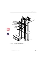
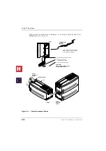
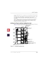
Make sure that the front and right side covers are removed from the cabinet (see
.
3.
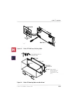
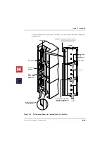
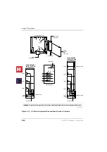
Slide the power supply into the right side of the cabinet so that its four mounting holes
align with the four cabinet mounting holes (see
). (Make sure that the two
backplane FG wires are positioned between the FG wire holder and the power supply.)
Note
The backplane FG wires are not safety grounds: they are required for proper system
Exchange line operation.
4.
Plug the Back Plane DC OUT cable plug into the DC OUT connector on the power
supply. (The plug has a guide key on it to ensure that it is plugged in correctly.)
5.
Secure the FG wire spade lug to the power supply with the FG screw.
6.
Secure the power supply to the cabinet with the four provided screws.
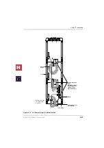
7.
If the cabinet is the Base Unit, a standalone Remote Expansion Cabinet, or the first in a
stack of Remote Expansion Cabinets. Set the Exp/Base switch to the “Base” position
(see
8.
If the cabinet is an Expansion Unit, set the Exp/Base switch to the “Exp” position.
Important!
The power supply set as “Base” is the master and has On/Off control over all
other power supplies, which are designated as slaves. If the master power
supply is turned Off or On, all other power supplies will automatically turn
Off or On. (Individual slave power supplies must be turned On.)
9.
See
to ensure that the power supply is properly installed.
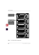
10. Install power supplies in all cabinets, using Steps 1~9 of this procedure.
11. Install the Base and optional Expansion Cabinets, ground wiring, and cabinet bonding
plates, AC and reserve power cabling, and PCB cabling per the
Installation Sequence” on Page 2-5
Note
Power Supply testing procedures are provided in the Fault Finding chapter, which
should be referred to if it is suspected that the power supply does not work properly.
Testing the System’s Power Supply
If the “AC” or “DC” LEDs fail to light in Steps 1 or 3, see the Circuit Breaker Reset
Proceedure on
-
1.
Plug the AC power cable into an outlet. The “AC” LED on the power supply lights
green.
2.
Turn On the DC power switch for the power supply. The “DC” LED on the power
supply lights green.
H
C
Summary of Contents for Strata CT
Page 36: ...Strata CT Configuration 1 22 Strata CT I M Manual October 2000 H C ...
Page 94: ...Strata CT Installation 2 58 Strata CT I M Manual October 2000 H C ...
Page 242: ...Peripheral Installation 6 54 Strata CT I M Manual October 2000 H C ...
Page 258: ...ACD Installation 7 16 Strata CT I M Manual October 2000 H C ...
Page 274: ...Fault Finding 8 16 Strata CT I M Manual October 2000 H C ...
Page 364: ...ISDN Interfaces 10 38 Strata CT I M Manual October 2000 H C ...
Page 370: ...Notes to Users A 6 Strata CT I M Manual October 2000 H C ...

