Strata CT Installation
2-8
Strata CT I&M Manual October 2000
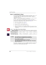
Power Supply (BPSU672F) Removal
1.
Remove the front and right side covers (
) from the cabinet. Remove the right
side covers of other cabinets as needed to disconnect wiring.
2.
Turn the power supply Off, and disconnect the AC power cord, all ground wiring and
reserve power cabling that is connected to the power supply.
3.
Disconnect the back plane DC OUT cable plug from the DC OUT connector.
4.
Loosen the four mounting screws securing the power supply to the cabinet and remove
the power supply.
Power Supply Replacement
➤
Install the replacement power supply per
“Install Power Supply” on Page 2-6
.
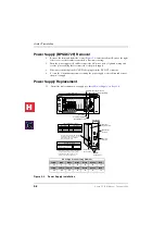
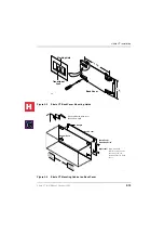
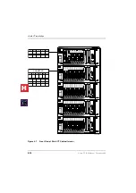
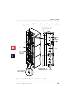
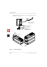
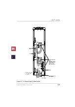
Figure 2-2
Power Supply Installation
DC Voltage Connector Plug Pin Wires
Yellow
Blue
White
Green
Green
Green
Red
-24
-5
+5
0
0
0
+5
Yellow
Yellow
Yellow
Green
Green
Green
Red
-24
-24
-24
0
0
0
+5
POW
+5V
-5V
P.F.
RESET
EXP
BASE
AC IN
BATT
DC OUT
-27V1
-27V2
-27V3
-27V4
+
-
POWER
ON
OFF
FG
B101
B102
S101
S102
S103
S104
S105
S106
S107
S108
5039
AC IN
BATT
-24V1
-24V2
-24V3
-24V4
+
-
POWER
ON
OFF
POW
+5V
-5V
P.F.
RESET
EXP
BASE
DC OUT
FG
DC Voltage
Connector Jack
DC Voltage Specification
+5V (+4.5 ~ +5.5), 4.0 amps
-5V (–4.5 ~ –5.5), 0.8 amps
Expansion Cabinet only
-24V (–26.3 ~ –27.8), 6.0 amps
BATT (Volts)
+
–
0
–26.3 ~ –27.8
1. Back Plane DC Voltage Plug must be plugged
into Power Supply when checking voltages.
2. On BPSU672, the BATT output is 0 volts
unless connected to good batteries.
Power Factor (PF) alarm LED indicates
the cabinet PF was exceeded. Correct
the problem and press the RESET
button to clear the alarm.
24V Circuit Breaker Assignments:
24V-1
24V-2
24V-3
24V-4
EXP. Cabinet
24V-1
24V-2
24V-3
24V-4
S101, S102
S103, S104
S105, S106
S107, S108
S_01, S_02
S_03, S_04
S_05, S_06, S_07
S_08, S_09, S_10
Base Cabinet
Mounting Holes
Expansion/
Base Switch
FG Frame
Ground Screws
Battery Cable
Connector
AC Power
Cord Jack
Back Plane DC Voltage Connector
Back Plane DC Voltage Cable/Plug
Green/Green yellow wire
fastened with FG Screw
Cabinet Support Post
Wire Clamp
2
H
C
Summary of Contents for Strata CT
Page 36: ...Strata CT Configuration 1 22 Strata CT I M Manual October 2000 H C ...
Page 94: ...Strata CT Installation 2 58 Strata CT I M Manual October 2000 H C ...
Page 242: ...Peripheral Installation 6 54 Strata CT I M Manual October 2000 H C ...
Page 258: ...ACD Installation 7 16 Strata CT I M Manual October 2000 H C ...
Page 274: ...Fault Finding 8 16 Strata CT I M Manual October 2000 H C ...
Page 364: ...ISDN Interfaces 10 38 Strata CT I M Manual October 2000 H C ...
Page 370: ...Notes to Users A 6 Strata CT I M Manual October 2000 H C ...

