41
Function setup
Karaoke Vocal
DVD
Off: The primary vocal is not output.
On: The primary vocal is output when it is recorded
on the disc.
Notes
• The vocal output feature is used during playback of
Dolby Digital (multi-channel) recorded DVD KARAOKE
discs. This feature allows you to turn off vocal audio
tracks, or restore them for background
accompaniment.
• When playing KARAOKE, connect appropriate audio
equipment such as an amplifier to the DVD video
player.
Audio Out Select
DVD
CD
Select the output sound format corresponding to your
system connection.
For details of sound recording systems, see
35
.
Bitstream:
Select when connected to an amplifier
equipped with a Dolby Digital, DTS,
MPEG1 or MPEG2 decoder.
18 19
The DVD video player outputs digital
audio information in the bitstream
format when you play a DVD video disc
recorded on the Dolby Digital, DTS,
MPEG1 or MPEG2 recording system.
Analog 2ch: Select when connected to a TV, or
Dolby Pro Logic or stereo system via
the analog audio jacks.
16 17 18
PCM:
Select when connected to a 2 channel
digital stereo amplifier.
19
The DVD video player outputs sounds
in the PCM 2ch format when you play a
DVD video disc recorded on the Dolby
Digital, MPEG1 or MPEG2 recording
system.
Dynamic Range Control
DVD
Off: Full dynamic range is maintained.
On: Dynamic range is reduced.
Notes
• This function works only during playback of Dolby
Digital recorded discs.
• The level of Dynamic Range Reduction may differ
depending on the DVD video disc.
Audio
Dynamic Range Control
Karaoke Vocal
Audio Out Select
Bitstream
On
Off
AB C
Summary of Contents for SD-110EB
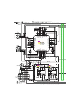
Page 80: ...4 2 Power Supply Block Diagram Fig 3 4 2 ...
Page 82: ...Fig 3 4 5 4 3 3 Front Display Power Switch Block Diagram ...
Page 83: ...µ Fig 3 4 6 4 4 Main Block Diagrams 4 4 1 Servo System Block Diagram ...
Page 84: ...Fig 3 4 7 4 4 2 Signal System Block Diagram ...
Page 85: ...Fig 3 4 8 4 5 Output RGB Block Diagram ...
Page 88: ...10 1 3 4 A B C D E G 2 5 6 7 8 9 F Fig 3 5 3 5 2 Front Display Power Switch Circuit Diagram ...
Page 91: ...5 3 2 Main Circuit Diagram Fig 3 5 5 ...
Page 92: ...5 3 2 Main Circuit Diagram ...
Page 93: ......
Page 94: ......
Page 95: ......
Page 96: ......
Page 97: ......
Page 98: ......
Page 99: ...Fig 3 5 5 ...
Page 101: ...10 1 3 4 A B C D E G 2 5 6 7 8 9 F Fig 3 5 7 5 4 Output RGB Circuit Diagram ...
Page 102: ...10 1 3 4 A B C D E G 2 5 6 7 8 9 F 5 5 Motor System Circuit Diagram Fig 3 5 8 ...
Page 120: ......


