Replacement Procedures
NOTE: Apply the silicon grease enough to cover the chip surface using the special
applicator.
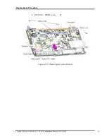
Figure 4-29
Applying silicon grease
6.
Install the
CPU heat sink
and
heat sink holder
and secure them with the following
screws
along 1 to 6.
M2.0
×
3.0
BIND
screw
x6
7.
Connect the
Heat sink cable
to the connector on the system board
NOTE: When securing the heat sink holder, be sure to secure the screws in the order of
the number marked on the holder.
Satellite U300 and Satellite Pro U300 Maintenance Manual (960-Q08)
49
Summary of Contents for Satellite Pro U300
Page 13: ...Satellite U300 and Satellite Pro U300 Maintenance Manual 960 Q08 13 ...
Page 14: ...Chapter 1 Hardware Overview ...
Page 48: ...2 1 CONFIDENTIAL Chapter 2 Troubleshooting Procedures ...
Page 49: ...2 2 CONFIDENTIAL Satellite U300 and Satellite Pro U300 Maintenance Manual 960 Q08 2 ...
Page 118: ...Test Program for Field Satellite U300 and Satellite Pro U300 Tests and Diagnostics Manual 17 ...
Page 172: ...Replacement Procedures 4 iiSatellite U300 and Satellite Pro U300 Maintenance Manual 960 Q08 ...
Page 228: ...Satellite U300 and Satellite Pro U300 Maintenance Manual 960 Q08 App i Appendices ...
Page 229: ...App ii Satellite U300 and Satellite Pro U300 Maintenance Manual 960 Q08 ...
Page 239: ...Handling the LCD Module A 6 Satellite U300 and Satellite Pro U300 Maintenance Manual 960 Q08 ...
Page 285: ...Display codes D 2 Satellite U300 and Satellite Pro U300 Maintenance Manual 960 Q08 ...
Page 307: ...Wiring Diagrams F 2 Satellite U300 and Satellite Pro U300 Maintenance Manual 960 Q08 ...
Page 311: ...Reliability I 2 Satellite U300 and Satellite Pro U300 Maintenance Manual 960 Q08 ...
Page 313: ...Reliability I 2 Satellite U300 and Satellite Pro U300 Maintenance Manual 960 Q08 ...


