background image


RemotEye II User Manual – 50024-014 

113 


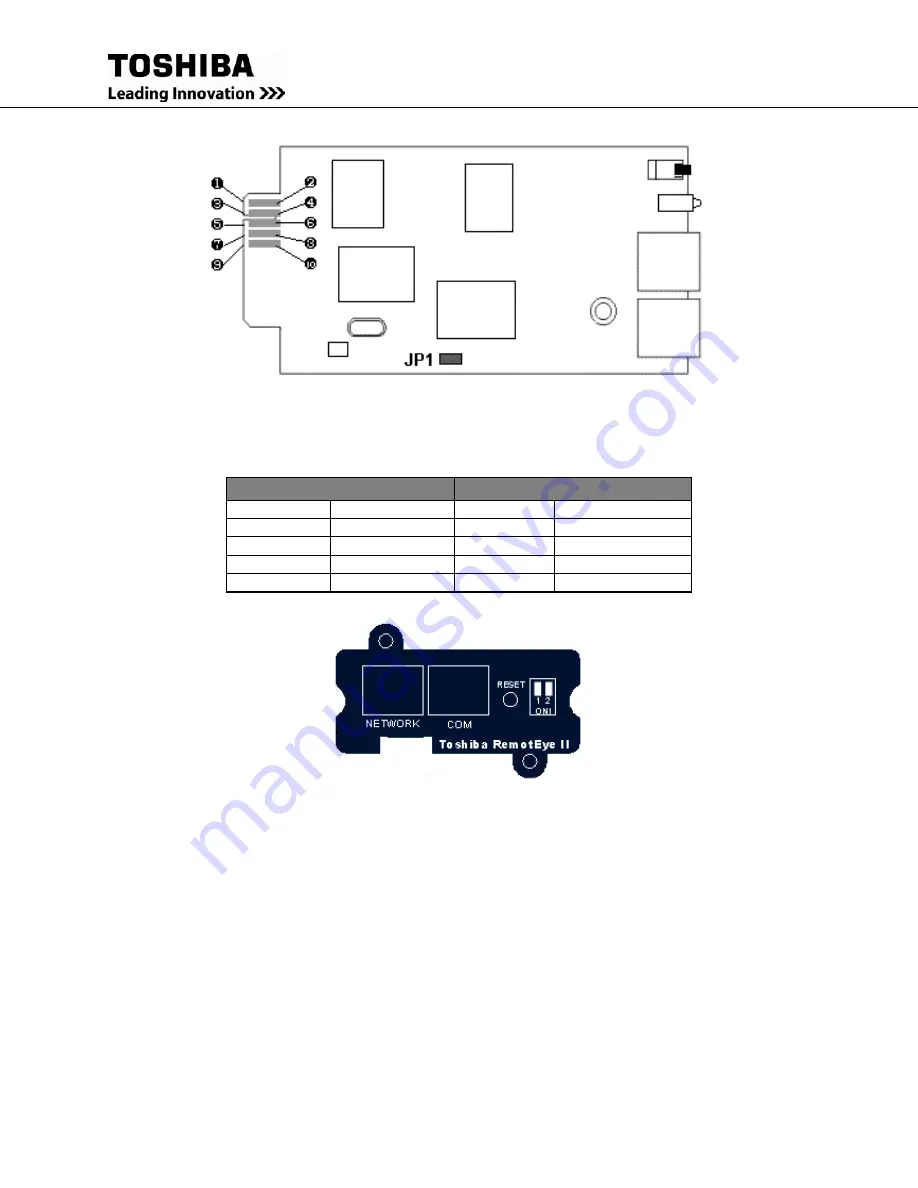
Figure 32: RemotEye II/Internal Top View 


Pin Assignment 

Bottom Side 

Component Side 

Pin 1 

GND 

Pin 2 

DC (7-16V) 

Pin 3 

Txd_UPS 

Pin 4 

Rxd_UPS 

Pin 5 

NC 

Pin 6 

NC 

Pin 7 

NC 

Pin 8 

Short to pin 10 

Pin 9 

GND 

Pin 10 

Short to pin 8 


Figure 33: RemotEye II/Internal Front View 

Summary of Contents for RemotEye II

Page 1: ......

Page 2: ...RemotEye II User Manual Document Number 50024 014 August 2015 ...

Page 3: ...ng operating or performing maintenance on this equipment The information in this manual is subject to change without notice The Toshiba International Corporation shall not be liable for direct indirect special or consequential damages resulting from the use of the information contained within this manual This manual is copyrighted No part of this manual may be photocopied or reproduced in any form...

Page 4: ... to provide application information The Support Center can be reached at 877 867 8773 toll free or 713 466 0277 The center is open from 8 a m to 5 p m CST Monday through Friday You may also contact TOSHIBA by writing to TOSHIBA International Corporation 13131 West Little York Road Houston Texas 77041 9990 For further information on TOSHIBA s products and services please visit our website at HTTP W...

Page 5: ... Corporation s UPS Division The warranty contained in the contract between the parties is the sole warranty of the TOSHIBA International Corporation s UPS Division and any statements contained herein do not create new warranties or modify the existing warranty Any electrical or mechanical modifications to this equipment without prior written consent of the TOSHIBA International Corporation will vo...

Page 6: ...ring the RemotEye II via Telnet 38 Connecting to the RemotEye II via Telnet 40 RemotEye II Telnet Menu Navigation 40 Configuring the RemotEye II via HTTP 41 Connecting to the RemotEye II via HTTP 42 RemotEye II Web Menu Navigation 43 Configuring the Remoteye II via SNMP 74 Connecting to the RemotEye II via SNMP 82 MIB 87 Toshiba RemotEye II Application Program 93 Toshiba RemotEye II Client Softwar...

Page 7: ...t safety information that must be carefully adhered to The word DANGER preceded by the safety alert symbol indicates that an imminently hazardous situation exists that if not avoided will result in death or serious injury to personnel The word WARNING in capital letters preceded by the safety alert symbol indicates that a potentially hazardous situation exists that if not avoided could result in d...

Page 8: ... and or strict adherence to the procedures to prevent serious injury to personnel or death Electrical Hazard Symbol A symbol which indicates a hazard of injury from electrical shock or burn It is comprised of an equilateral triangle enclosing a lightning bolt Explosion Hazard Symbol A symbol which indicates a hazard of injury from exploding parts It is comprised of an equilateral triangle enclosin...

Page 9: ...ined in this instruction manual DO NOT remove or cover any of the labels If the labels are damaged or if additional labels are required contact your Toshiba representative for additional labels Labels attached to the equipment are there to provide useful information or to indicate an imminently hazardous situation that may result in serious injury severe property and equipment damage or death if t...

Page 10: ...ng to the construction installation operation and maintenance of the electrical equipment and has received safety training on the hazards involved Refer to the latest edition of NFPA 70E for additional safety requirements Qualified Personnel shall Have read the entire operation manual of the system being serviced Be trained and authorized to safely energize de energize ground lockout and tag circu...

Page 11: ...ation Install the unit where the ambient temperature is within the specified range Do not install the unit in areas that are subject to high humidity Do not install the unit in areas that allow exposure to direct sunlight Do not install the unit in areas that allow exposure to high levels of airborne dust metal particles or flammable gases Do not install the unit in areas near sources of electrica...

Page 12: ...tion and operation of the RemotEye II The RemotEye II is available as a circuit board that is inserted into the option slot of the UPS or as an external device that connects to the UPS via a provided cable The RemotEye II Internal is designed for the Toshiba UPS that has the option slot The circuit board is connected to the UPS via the RemotEye II Internal card edge connector The RemotEye II Exter...

Page 13: ... containing the following Toshiba mib the Toshiba version 1 2 MIB file RFC1628 compatible Tupgrade exe the RemotEye II upgrade utility Tsb4xx bin the Current RemotEye II image file Window exe Toshiba RemotEye II Client Software installation file for Window Unix exe Toshiba RemotEye II Client Software installation file for UNIX OS and RemotEye II User Manual in PDF format PC cable a DB9 female to R...

Page 14: ...b4xx bin the Current RemotEye II image file Window exe Toshiba RemotEye II Client Software installation file for Window Unix exe Toshiba RemotEye II Client Software installation file for UNIX OS and RemotEye II User Manual in PDF format PC cable a DB9 female to RJ45 cable Workstation COM port to RemotEye II External PC port UPS cable a DB9 male to RJ45 cable Toshiba UPS RS232 port to RemotEye II E...

Page 15: ...TC This clock is used for time stamping of its data log and for executing any scheduled events UPS Event Notification RemotEye II sends out notification of UPS events via Email SNMP Traps and Java Applets Graphic User Interface GUI User friendly GUI for web pages and Java applets Power Quality Monitor Java applets provide on screen visual indication of power quality through dynamic graphics Versat...

Page 16: ...s to save logs from several RemotEye s at the same time to a same or different computer Client Shutdown The Toshiba RemotEye II Client Software can broadcast system failure messages via an IP Internet Protocol packet and perform unattended shutdown of up to 32 clients operating under a variety of platforms Environmental Monitoring Device EMD Optional EMD allows monitoring of the environment temper...

Page 17: ...Windows 95 98 NT 2000 XP Vista Macintosh and Unix The RemotEye II supports the following Toshiba UPS system families 1000 Series External RemotEye II requires a null modem cable 1400 S E Plus 1400 XL Plus 1400 Super XL Plus Series 1500 Plus Series 1600 Plus Series 1700 Plus Series 1800 Plus Series 4200 Plus Series G8000 Series G8000MM Series G9000 Series ...

Page 18: ...rnal card 1 Turn the UPS off using the proper shutdown procedure as explained in the UPS manual 2 Slide the RemotEye II Internal printed circuit board into the extension option slot of the UPS 3 Secure the printed circuit board using the UPS supplied screws See Figure 1 RemotEye II Internal Figure 1 RemotEye II Internal ...

Page 19: ... RemotEye II into the 12 VDC power receptacle of the RemotEye II device 2 Plug the RemotEye II power adapter into a 120 220 VAC power source For best results be sure outlet is powered by a Toshiba UPS 3 Connect the UPS cable from the RS232 serial port of the Toshiba UPS to the RemotEye II External UPS port See Figure 2 RemotEye II External Figure 2 RemotEye II External ...

Page 20: ...nect one end of a Category 5 cable to the NETWORK RJ45 receptacle of RemotEye II 2 Connect the other end of the Category 5 cable to a designated network switch or hub A network administrator will allocate an available port 3 Verify a network link has been established On RemotEye II External confirm Traffic LED on RemotEye II is illuminated On RemotEye II Internal confirm the leftmost green LED is ...

Page 21: ...a network The MAC address sometimes called the physical address is made up of 6 hexadecimal bytes A label marked with the MAC address is included with each RemotEye II This label is affixed to the bottom of every RemotEye II External and this label is affixed to the top of every RemotEye II Internal printed circuit board For each RemotEye II the MAC address is created using the following format 00...

Page 22: ...cimal value of the NN MAC address byte Example A RemotEye II MAC address of 00 E0 D8 0C 01 3F would have a default IP address of 172 18 1 63 This places RemotEye II on a 172 18 0 0 IP network Default Network Mask The RemotEye II is initially configured with a default Network Mask This default value is always 255 255 0 0 This places RemotEye II on a Class B network Default Gateway The RemotEye II i...

Page 23: ...tup the hardware for direct RemotEye II configuration Connect the DB9 female end of the PC cable to the terminal or workstation COM port Connect the RJ45 end of the PC cable to the PC port of RemotEye II External or the COM port of the RemotEye II Internal Software Setup The direct configuration is accomplished by using the RS232 communication protocol The direct communication can be performed fro...

Page 24: ...or packaged with all Windows operating systems except Vista Launch the HyperTerminal program by navigating to Start Programs Accessories HyperTerminal HyperTerminal and follow the prompts Enter a name and select an icon for the application at the Connection Dialog box Select a direct connection to an appropriate com port listed in the pull down menu Ensure that the Properties dialog box is setup a...

Page 25: ...ns see the Main Menu Description on Figure 4 Console Main Menu and their submenus are discussed in more detail in the next section TIC RemotEye II Main Menu 1 TIC RemotEye Configuration 2 SNMP Communities 3 SNMPV3 USM Table 4 Trap Receiver Table 5 Reset Configuration To Default 6 Save and Exit 7 Save and Restart Agent Please Enter Your Choice Figure 4 Console Main Menu ...

Page 26: ... and Time 0 Return to Previous Menu 2 Control Group 1 HTTP Login Username 2 Community Read On1y 3 Community Read Write 4 BOOTP DHCP Control 5 Telnet Control 6 Network Upgrade Control 7 HTTP Security Control 8 SNMP Version Control 0 Return to Previous Menu 3 Parameter Group 1 System Contact 2 System Name CID 3 System Location 4 Poll Rate 0 Return to Previous Menu 4 Email Group 1 Mail Server 2 User ...

Page 27: ...V3 USM Table 1 Modify Table Entry 2 Reset to Default Setting 0 Return to Previous Menu 4 Trap Receiver Table 1 Modify Table Entry 2 Reset to Default Setting 0 Return to Previous Menu 5 Reset Configuration to Default 6 Save and Exit 7 Save and Restart Agent Table 1 Menu Map for RemotEye II Console ...

Page 28: ...NMPv3 USM Table 4 Trap Receiver Table 5 Reset Configuration to Default 6 Save and Exit 7 Save and Restart Agent Press the number of the associated selection and press Enter TIC RemotEye II Main Menu 1 TIC RemotEye II Configuration 2 SNMP Communities 3 SNMPV3 USM Table 4 Trap Receiver Table 5 Reset Configuration To Default 6 Save and Exit 7 Save and Restart Agent Please Enter Your Choice Figure 5 C...

Page 29: ...tEye II Configuration option provides access to the following system settings 1 System Group 2 Control Group 3 Parameter Group 4 Email Group 5 EMD Group 0 Return to Previous Menu TIC RemotEye II Configuration Menu 1 System Group 2 Control Group 3 Parameter Group 4 Email Group 5 EMD Group 0 Return to previous menu Please Enter Your Choice Figure 6 Console Configuration Menu Description ...

Page 30: ...motEye II supports the Network Time Protocol NTP and NTP Time Zone features These two features enable the UPS to synchronize its date and time with a NTP server and with the options of daylight saving time control see Figure 8 Date Time Menu Description 0 Return to Previous Menu System Group Menu RemotEye II Agent Version TIC RemotEye II v3 00 Ethernet address 00 E0 D8 08 80 0D 1 Ip Address 172 18...

Page 31: ...et applications The default setting is Enabled 6 Network Upgrade Control This parameter is used to enable or disable the Trivial File Transfer Protocol image upgrade When disabled RemotEye II will block any attempts to upgrade The default setting is Disabled 7 HTTP Security Control This parameter is used to enable or disable the web password protection feature When enabled a password is required t...

Page 32: ...e II This string serves as the RemotEye II Client Identifier CID in DHCP systems 3 System location The RemotEye II physical location 4 Poll Rate The polling rate in seconds This determines how frequently RemotEye II updates its data from the Toshiba UPS The default setting is 5 0 Return to previous menu NOTE System will label each event email with the system Name and Location in the format systemN...

Page 33: ...rt This parameter is used to set the time to send RemotEye II daily status report 7 Mail Receivers RemotEye II sends email notification to four recipients The recipients include users who use Short Message System SMS in Email address format such as phonenumber telcompany com Mail Account This parameter is used to enter the recipients email Address Mail Type 1 None Disable option to send email to r...

Page 34: ...itical points Users also have the options to setup the hysteresis and calibration offset from this group 3 Alarm 1 Group The Alarm 1 Group provides the option to setup this dry contact as normal close normal open high active low active and disabled 4 Alarm 2 Group The Alarm 2 Group provides the option to setup this dry contact as normal close normal open high active low active and disabled 5 Devic...

Page 35: ...as follows IP Address IP address of the NMS Community String NMS Get Set Community String Please refer to SNMP Get Set Criteria on page 82 for a more detailed explanation on Get Set Access Select Access Type 1 Read Only 2 Read Write 3 NoAccess IP Address Community String Access 1 0 0 0 0 No Access 2 0 0 0 0 No Access 3 0 0 0 0 No Access 4 0 0 0 0 No Access 5 0 0 0 0 No Access 6 0 0 0 0 No Access 7...

Page 36: ...The security level provides the following 3 options 1 noAuthNoPriv with no authentication and no privacy passwords 2 authNoPriv with authentication password but no privacy password 3 authPriv with no authentication password but with privacy password Authentication format The authentication format provides the following options 1 HMAC MD5 2 HMAC SHA Status Type The status shows the authentication s...

Page 37: ... shall be as follows IP Address IP address of the NMS Community String NMS community string Select Trap Type 1 None 2 Toshiba Trap 3 JEMA Trap 4 RFC 1628 Trap Description Description of the NMS IP Address Community String Trap Type Description 1 0 0 0 0 2 0 0 0 0 3 0 0 0 0 4 0 0 0 0 5 0 0 0 0 6 0 0 0 0 7 0 0 0 0 8 0 0 0 0 1 Modify Modify an entry of table 2 Reset Reset an entry to default from tab...

Page 38: ...om the Main Menu press 4 to access the Reset Configuration to the Original Setting screen Save and Exit Main Menu 6 Save and Exit When executed the system saves the RemotEye II configuration and exits the program The new configuration takes effect immediately Save and Restart Agent Main Menu 7 Save and Restart Agent When executed the system saves the RemotEye II configuration and restarts the Remo...

Page 39: ...ork Connection on page 19 Software Setup The telnet configuration is accomplished through a TCP IP network connection A telnet connection can be established with RemotEye II by using any telnet application Follow these steps to setup the software for telnet RemotEye II configuration Verify workstation is loaded with Telnet application Verify a valid network path exists between the RemotEye II and ...

Page 40: ...mple Route Addition Windows operating systems provide the command Route Add for adding network routes Assume the default IP Address of the RemotEye II is 172 18 1 63 and assume the IP Address of the workstation is 210 67 192 147 To add the appropriate network route between these two devices follow these steps Turn on the workstation and setup the TCP IP protocol if necessary Enter the following co...

Page 41: ...s Enter 3 Key in the password default is public when prompted For more information on using telnet please refer to telnet application Windows help The RemotEye II will only accept 2 telnet clients simultaneously The telnet connection will time out after 60 seconds of inactivity RemotEye II Telnet Menu Navigation The configuration menus for telnet configuration are identical to those presented by a...

Page 42: ... unable to access the RemotEye II due to a firewall contact the network administrator for information on bypassing the firewall of the LAN The HTTP Security Control setting may also affect the user s ability to access the RemotEye II The HTTP Security Control setting may be set or viewed from Main Menu 1 TIC RemotEye II Configuration 2 Control Group 7 HTTP Security Control If the HTTP Security Con...

Page 43: ...on to configure RemotEye II 2 Click the Become Super User button at the bottom of the screen Enter TOSHIBA as the login name and public as the password case sensitive Non DHCP users continue on to step b DHCP users may skip steps b to d 3 Enter the RemotEye II IP address 4 Enter the RemotEye II Gateway address in the network 5 Enter the RemotEye II Network Mask of the network 6 Enter the IP addres...

Page 44: ...S Mode This field shows the present UPS system mode These readings include Other None On Line Bypass Battery Testing and Output Shutdown Input Voltage This field shows the present UPS input voltage in VAC Output Voltage This field shows the present UPS output voltage in VAC Output Load This field shows the present UPS load in of kVA Battery Capacity Remaining option This field shows the present re...

Page 45: ...o UPS Configuration menu UPS Firmware Revision This field shows the revision of the UPS firmware UPS RemotEye II Agent Revision This field shows the revision of RemotEye II UPS Manufacturer This field shows the name of the UPS manufacturer UPS Attached Devices This field shows the administrator configured description of the load devices that attached to the UPS e g computers communication devices ...

Page 46: ... remaining minutes of the UPS to sustain the current load Battery Voltage This field shows the battery voltage in VDC Battery Voltage Percent This field shows the battery voltage in Battery Current option This field shows the present battery current in Battery Temperature option This field shows the internal UPS temperature expressed in o C Battery Last Replaced Date This field shows the last repl...

Page 47: ...eld shows the UPS input voltage in VAC Max Input Voltage During Last 60 Seconds This field shows the maximum UPS input voltage during the last 60 seconds Min Input Voltage During Last 60 Seconds This field shows the minimum UPS input voltage during the last 60 seconds Input Current option This field shows the present UPS input current in Amps Input Active Power option This field shows the present ...

Page 48: ...t These readings include Other None On Line Bypass Battery and Output Shutdown Output Voltage This field shows the UPS output voltage in VAC Output Load This field shows the UPS load as a percentage of the maximum load setting Output Active Power This field shows the present UPS output active power in Watts Output Apparent Power This field shows the present UPS apparent power in VA Output Power Fa...

Page 49: ... UPS alarms Lastest Alarm This field shows the last recorded UPS alarm Alarm ID This field shows the sequential number associated with the alarm it indicates the activation sequence of the alarms This number will be reset after a RemotEye II reboot Alarm Time This field shows the RemotEye II alarm time stamp This value is displayed in the hh mm mm dd yyyy format Note The time depends on the RemotE...

Page 50: ...e II Shutdown Application that are presently registered with the RemotEye II Up to 32 clients may be registered at one time Index This field shows the serialized index numbers of the RemotEye II registered clients that are running during the execution of the RemotEye II Shutdown application IP Address This field shows the IP addresses of the registered clients of the RemotEye II Client Name This f...

Page 51: ...ltage This field allows the user to view the expected output frequency for the UPS Output Frequency This field allows the user to view the expected output frequency for the UPS Output VA Rating This field allows the user to view the maximum output VA rating defined as the maximum output voltage multiplied by the maximum output current of the UPS Output Power Rating This field allows the user to vi...

Page 52: ...un Inverter Mode option This option switches the UPS between the Run Inverter mode and the Bypass or Stop mode UPS Auto Start after Input Power Recovery Control This field allows the administrator to enable or to disable the auto start feature of the UPS Enabled this control will switch the UPS system to Run Inverter after power recovery from power failure UPS Auto Retransfer Control option This f...

Page 53: ...is displayed in the hh mm ss 24 hour format i e 8 30 p m is 20 30 00 Last Test Elapsed Time This field shows the elapsed time in seconds of the last battery test Last Test Results This field shows the test results of the last battery test Battery Test Command None No action Quick Test 10 sec Perform battery test for ten seconds Cancel Test Cancel the battery test not more than 1 minute Clear Test ...

Page 54: ...r to set the day of the week that the battery test is to be performed or to view the current setting Test Time This field allows the administrator to set the time that the battery test is to be performed or to view the current setting This value is displayed in the in hh mm format Action This field shows the battery test type options Available options are None No action Quick Test 10 sec Quick tes...

Page 55: ...nt Warning A warning message will be broadcast to the connected clients Client Shutdown A warning message will be broadcast and the shutdown command will be sent to the connected clients UPS Output Shutdown A warning message will be broadcast the output shutdown command will be sent to the connected clients and the UPS will be set to output shutdown Shutdown Delay min This field allows the adminis...

Page 56: ...ws the action taken upon detection of a UPS Overload condition Default Warning The UPS Overload setting may be viewed from the UPS Configuration menu UPS Over Temperature This field shows the action taken upon detection of a UPS over temperature condition Default Warning Recurring On Off Schedule This field shows the programmed Recurring On Off Schedule setting Default Disabled Non Recurring On Of...

Page 57: ...s the administrator to set the day of the week to output shutdown restart the UPS or to view the current setting The schedules are configured in the same day format Output Shutdown Time This field allows the administrator to configure the UPS to output shutdown or to view the current settings This value is displayed in the hh mm ss 24 hour format i e 8 30 p m is 20 30 00 Restart Time This field al...

Page 58: ...e of the UPS output shutdown or to view the current setting Output Shutdown Time This field allows the administrator to set the UPS shutdown time This value is displayed in the hh mm ss 24 hour format i e 8 30 p m is 20 30 00 Restart Date This field allows the administrator to configure the UPS restart date or to view the current setting Restart Time This field allows the administrator to configur...

Page 59: ...allows the administrator to set the IP address of the network DNS server if a Hostname is entered for the Mail Server Otherwise this field can be 0 0 0 0 Mail Daily Status Report At hh mm This field allows the administrator to set the time to send a Daily Status report to select email address Mail Accounts The time is set in 24 hour format Mail Account This field allows the administrator to set th...

Page 60: ... be used to adjust the sensitivity of an alarm The alarm will be active or inactive only after the alarm stays in the same state for the duration of the hysteresis value in seconds For example if the hysteresis is 5 for an alarm the alarm will NOT activate until the same state has persisted for 5 seconds This ruling also applies in reverse so that the alarm has to stay in an inactive state for 5 s...

Page 61: ...4 The EMD can be configured as Disabled or Auto The setup should be configured as Disabled if an EMD is not attached to the port The EMD type will be auto detected by the EMD if configured as Auto and if the EMD is plugged into the port ...

Page 62: ...The date value is displayed in the MM DD YYYY format i e Jan 18 2005 is 01 18 2005 The time value is displayed in the hh mm ss 24 hour format i e 8 30 p m is 20 30 00 Synchronize with computer time This field allows the administrator to synchronize the RemotEye II date and time to the computer clock which the end user is using Synchronize with NTP server NTP server IP and correct time zone must be...

Page 63: ...will label each event email with the system Name and Location in the format systemName SystemLocation System Location This field allows the administrator to set the value in System installation place System Location that is defined in MIB II or to view the current setting History Log Interval This field allows the administrator to set the polling time in seconds of the Input Voltage Output Voltage...

Page 64: ...trol process i e telnet 192 168 7 18 Network Upgrade This field allows the administrator to Enable Disable the Trivial File Transfer Protocol TFTP upgrade control or to view the current setting The Windows upgrade utility Tugrade may be used to upgrade the RemotEye II when enabled Reset the RemotEye II to Default This field allows the administrator to Enable Disable the RemotEye II Reset function ...

Page 65: ...figured i e An entry of 192 168 7 255 indicates clients with IP address within the range of 192 168 7 0 to 192 168 7 255 are valid network management stations set by the user Community String This field allows the administrator to set the low level password of the associated IP address or to view the current setting Access Type This field allows the administrator to set the access type for the cli...

Page 66: ...set the authentication password of the associated user Privacy Password This field allows the administrator to set the privacy password of the associated user Security This field allows the administrator to set the access type for the user 1 noAuthNoPriv with no authentication and no privacy passwords 2 authNoPriv with authentication password but no privacy password 3 authPriv with no authenticati...

Page 67: ...g This field allows the administrator to set the community string of the trap s PDU to be sent or to view the current setting The maximum length of the string is 19 characters Trap Type This field allows the administrator to set the types of traps to be received or to view the current settings Setting options are None Traps are not being received Toshiba Trap Traps are received based on the Toshib...

Page 68: ...w the current setting Input Group Page This field allows the administrator to set the refresh rate in seconds of the Input Parameters menu or to view the current setting Output Group Page This field allows the administrator to set the refresh rate in seconds of the Output Parameters menu or to view the current setting Alarm Group Page This field allows the administrator to set the refresh rate in ...

Page 69: ...e This field shows the UPS output voltage in VAC Load Pecentage This field shows the UPS load in Battery Voltage This field shows the battery voltage in VDC Output Status This field shows the status of the output status These readings include Other None On Line Normal Bypass Battery Shutdown UPS Extended Log This page provides a consolidated view of the UPS parameters that have been taken over a s...

Page 70: ...he average UPS load values of the consolidated interval Battery Voltage This field shows the minimum maximum and the average battery voltage levels of the consolidated interval UPS Events Log This table lists the UPS events since the table was last cleared The existing values are overwritten when the maximum number of entries has been reached The log data may be cleared from the Clear Save Log Dat...

Page 71: ... csv extension which allows it to be opened using Microsoft Excel Specific log data may be cleared by the user or the entire log data record may be cleared after saving the csv file Clear Log Data This field allows the administrator to the clear log data by checking the applicable box and clicking the Clear button Clear Log Data after saving the log file The log data may be cleared after saving th...

Page 72: ...left side of the RemotEye II home page Figure 17 HTTP Monitor Screen on page 71 will open in a separate window The Monitor applet provides a visual representation of the UPS system It contains a status bar that can display the current UPS status an alarm window that can display the current UPS alarms and a display of the following UPS key parameters Input Voltage Input Frequency UPS Output Battery...

Page 73: ...displayed on the same graph The user may select any combination of parameters to be displayed on the graph by clicking the check box beside a parameter on the monitor screen and clicking the Refresh button Display Point Displays the log interval on the graph Refresh Click the Refresh button after changing any settings on the History page for the changes to take effect Reload Updates the History pa...

Page 74: ...graph The user may select any combination of parameters to be displayed on the graph by clicking the check box beside a parameter on the monitor screen and clicking the Refresh button Display Point Displays the log interval on the graph Refresh Click the Refresh button after changing any settings on the UPS History Log Monitor for the changes to take effect Reload Update the UPS History Log Monito...

Page 75: ...a Manager The Agent collects information about a network node The Manager collects information from the Agent The RemotEye II provides an Agent for a Toshiba UPS The Manager is a software application that is provided separately A workstation running Manager software is considered a Network Management Station NMS There are many Manager applications available Some commonly used applications are list...

Page 76: ... the network of the NMS For instruction on defining which gateway RemotEye II uses consult the System Group section on page 29 The MIB System Group of RemotEye II must match that of the NMS see the section titled System Group on page 29 for further information This parameter will allow an NMS within the group to access RemotEye II data Granting Write Access The RemotEye II controls permissions for...

Page 77: ... Workgroup Node Manager From the Control pull down menu click SNMP Manager Manage Database Select map to the MIB file Toshiba mib on the included CDROM click ADD Click Close to close the SNMP Manager Database Specifying Trap Receivers To send traps to an NMS the NMS must be designated as a trap receiver of the RemotEye II See Trap Receiver Table section on page 36 for instruction on defining a tra...

Page 78: ...ap 2 Attribute 1 MIB value upsTestID Integer value that represents the test This number resets to value 0 each time RemotEye II is reset Attribute 2 MIB value upsTestSpinLock Integer value that acts as a key granting or refusing permission to initiate a test Attribute 3 MIB value upsTestResultsSummary Integer value that represents the results of a test Specific Trap 3 Attribute 1 MIB value upsAlar...

Page 79: ...PLY 0 Start HP OpenView Workgroup Node Manager Open the Customize Traps Alarms from the Monitor Customize Trap pull down menu Click Add Devices Class and select Toshiba RemotEye II Click the Add Trap button Add specific traps 1 through 4 as desired The table below suggests messages to use for each specific trap Trap Conditions Customized Traps Description 6 Specific 1 on Battery time 1 2 3 6 Speci...

Page 80: ...o a supportive level 5 upsAlarmTempBad The UPS is overheating Check for UPS fan failure or high ambient temperature 40 C 104 F The UPS is no longer overheating 6 upsAlarmInputBad The input voltage is out of tolerance UPS may switch to Battery Mode to support the load The input voltage is back within tolerance 7 upsAlarmOutputBad The output voltage is out of tolerance Check the output voltage N A 8...

Page 81: ... A N A 22 upsAlarmShutdownPendin g A UPS output shutdown command has been issued Output will turn off after delay OK 23 upsAlarmShutdownImmine nt The UPS output will be shutdown in less than 30 seconds due to previously issued shutdown command N A 24 upsAlarmTestInProgress A UPS battery test is in progress Battery test completed 25 upsAlarmPhaseRotation Input phase rotation is incorrect Check inpu...

Page 82: ...ination of fault The cause of the DC bus undervoltage condition has been removed The UPS is no longer at fault 32 upsAlarmOutputUnderVolt age UPS reporting output Undervoltage Contact Toshiba authorized service center for examination of fault The cause of the output undervoltage has been removed The UPS is no longer at fault 33 upsAlarmOutputOverVolta ge UPS reporting output Overvoltage Contact To...

Page 83: ...e II If a get request matches either the Community Read Only or the Community Read Write values the request is honored A set however is only allowed if the request includes the Community Read Write value NMS Listed in SNMP Communities If the NMS appears in the SNMP Communities with Read or Read Write Access rights the corresponding community name and privileges listed within this table in conjunct...

Page 84: ...ted in the SNMP Communities using one of the global community strings SNMP Communities settings 1 172 18 63 1 ronly Read Write Analysis Both get and set requests from this NMS will be honored when using the ronly community string Any requests from NMS using rwrite however will be denied Case 4 NMS is listed in the SNMP Communities multiple times using the same community string SNMP Communities set...

Page 85: ...tication of any password enables writing its respective table For example upsConfigPassword protects the writable parameters of the upsConfig table Authenticating this password enables writing ability to parameters within the upsConfig table The next authentication of this password disables writing ability to parameters within the upsConfig table The general progression for altering any parameters...

Page 86: ...85 Description upsPassword This MIB object protects the upsPassword group upsPasswordControlPassword This MIB object controls the value of upsControlPassword upsPasswordCurrent Password This MIB object controls the value of upsPassword ...

Page 87: ...swordControlPassword depending on which password requires alteration Send an SNMP set request of upsPasswordAccess to RemotEye II This disables the upsPassword table and secures the passwords Default Passwords The default values for the passwords are upsPasswordAccess The default value is toshibA factorY passworD However this MIB object will always accept the value of upsPasswordCurrent Password a...

Page 88: ... 1212 DisplayString FROM RFC1213 MIB TRAP TYPE FROM RFC 1215 toshiba OBJECT IDENTIFIER enterprises 186 equ OBJECT IDENTIFIER toshiba 1 equUPS OBJECT IDENTIFIER equ 19 ticUPS OBJECT IDENTIFIER equUPS 2 sp1 OBJECT IDENTIFIER ticUPS 1 upsIdent OBJECT IDENTIFIER sp1 1 upsBattery OBJECT IDENTIFIER sp1 2 upsInput OBJECT IDENTIFIER sp1 3 upsOutput OBJECT IDENTIFIER sp1 4 upsBypass OBJECT IDENTIFIER sp1 5...

Page 89: ... 186 1 19 2 1 2 11 upsBatteryRatedHoldingTime OBJECT TYPE 1 3 6 1 4 1 186 1 19 2 1 2 12 upsInput 1 3 6 1 4 1 186 1 19 2 1 3 upsInputLineBads OBJECT TYPE 1 3 6 1 4 1 186 1 19 2 1 3 1 upsInputNumLines OBJECT TYPE 1 3 6 1 4 1 186 1 19 2 1 3 2 upsInputTable OBJECT TYPE 1 3 6 1 4 1 186 1 19 2 1 3 3 upsInputEntry OBJECT TYPE 1 3 6 1 4 1 186 1 19 2 1 3 3 1 upsInputLineIndex OBJECT TYPE upsInputFrequency ...

Page 90: ...putOverload OBJECT TYPE 1 3 6 1 4 1 186 1 19 2 1 6 3 8 upsAlarmOnBypass OBJECT TYPE 1 3 6 1 4 1 186 1 19 2 1 6 3 9 upsAlarmBypassBad OBJECT TYPE 1 3 6 1 4 1 186 1 19 2 1 6 3 10 upsAlarmOutputOffAsRequested OBJECT TYPE 1 3 6 1 4 1 186 1 19 2 1 6 3 11 upsAlarmUpsOffAsRequested OBJECT TYPE 1 3 6 1 4 1 186 1 19 2 1 6 3 12 upsAlarmChargerFailed OBJECT TYPE 1 3 6 1 4 1 186 1 19 2 1 6 3 13 upsAlarmUpsOut...

Page 91: ...7 7 4 upsDeepBatteryCalibration OBJECT TYPE 1 3 6 1 4 1 186 1 19 2 1 7 7 5 upsControl 1 3 6 1 4 1 186 1 19 2 1 8 upsShutdownType OBJECT TYPE 1 3 6 1 4 1 186 1 19 2 1 8 1 upsShutdownAfterDelay OBJECT TYPE 1 3 6 1 4 1 186 1 19 2 1 8 2 upsStartupAfterDelay OBJECT TYPE 1 3 6 1 4 1 186 1 19 2 1 8 3 upsRebootWithDuration OBJECT TYPE 1 3 6 1 4 1 186 1 19 2 1 8 4 upsAutoRestart OBJECT TYPE 1 3 6 1 4 1 186...

Page 92: ...186 1 19 2 1 9 18 upsConfigLowVoltageTransferPoint OBJECT TYPE 1 3 6 1 4 1 186 1 19 2 1 9 19 upsConfigHighVoltageTransferPoint OBJECT TYPE 1 3 6 1 4 1 186 1 19 2 1 9 20 upsConfigBattInstalledDate OBJECT TYPE 1 3 6 1 4 1 186 1 19 2 1 9 21 upsConfigNumBattSeries OBJECT TYPE 1 3 6 1 4 1 186 1 19 2 1 9 22 upsConfigNumBattStrings OBJECT TYPE 1 3 6 1 4 1 186 1 19 2 1 9 23 upsConfig1BattVoltage OBJECT TY...

Page 93: ...92 RemotEye II User Manual 50024 014 upsTrapAlarmEntryAdded TRAP TYPE Variables upsAlarmId upsAlarmDescr upsTrapAlarmEntryRemoved TRAP TYPE Variables upsAlarmId upsAlarmDescr END ...

Page 94: ...sages on the screen of the servers and then shutdown the server gracefully Installation of RemotEye II Client using Windows 9x 2000 NT XP Insert the RemotEye II CD ROM into the CD ROM drive Run the Installer exe program on the CD ROM A dialog box will be displayed on the screen type in the IP address of the designated RemotEye II its Client Name and its Shutdown Delay Time Click the Def button to ...

Page 95: ...ample browse http 172 18 1 63 Select Connected Client Table from UPS Monitoring of the main menu and the list of the connected devices will be shown on the screen Figure 21 HTTP Connected Client Table Figure 21 HTTP Connected Client Table Note The client local shutdown delay must not be greater than the UPS shutdown delay configured in RemotEye II ...

Page 96: ...is selected after the counter has counted down to zero Figure 22 Toshiba RemotEye II Client Software Shutdown Warning Message There are five kinds of state for Toshiba RemotEye II Client Software UPS Connection OK Green Background Trying to locate UPS Blue Background Local machine is about to shut down Red Background The service is suspended Green Background Remote UPS is about to shut down or has...

Page 97: ...ia RemotEye The configuration phase will guide user to reconfigure the setting that is made in installation phase Program Overview When installing this program the shutdown shell application will check the target machine s Operating System OS and determine whether it is a predefined OS from the recognized OS list If it is not the user will be prompted to answer some questions regarding system info...

Page 98: ...r will be prompted the following questions questions 3 8 3 dev is your system device directory y n If n is selected 4 Input device directory Using rsh for remote shell y n If n is selected 5 Input remote shell Using sbin init0 to shut down your system y n If n is selected 6 Input shut down command Please input your system s initial directory at boot time Please input run level s directory to boot ...

Page 99: ...the following action Usage uGuard sh h v s S u U d l e g where h This manual page v Show revision information s Start the program now S Start the program at next boot up time u Unload program U Unload program don t restart at next boot time d Suspend program l List configurations e Modify configurations g See log var log usha ug_usha log ...

Page 100: ...st configuration process this phase will show the last setting value as a default setting Input USHA IP Address Input Client Name Warning Beep On y n Shutdown delay time is 120 seconds y n If n is selected Input shut down delay time Shut down script is loaded y n If n is selected Input shut down script Force shut down delay time is 120 seconds y n If n is selected Input force shut down delay time ...

Page 101: ...his section highlights the manners in which RemotEye II can be used in conjunction with a UPS to manage power to UPS loads Set UPS to Output Shutdown Mode After Delay Administrators can issue an output shutdown to Toshiba UPS via RemotEye II in any cases To issue an output shutdown command go to UPS Control in the UPS Management menu Login as an administrator Select the radio button beside Set UPS...

Page 102: ...ely go to UPS Control on page 51 in the UPS Management menu Then login as an administrator and select the radio button beside Set UPS to Run Inverter Mode After Delay Lastly click the Apply button Scenario UPS Run Inverter Mode Delay mins 1 min default Set UPS to Run Inverter Mode After Delay 22 20 00 22 20 00 22 21 00 INVERTER OUTPUT SHUTDOWN ...

Page 103: ...ge in UPS Management menu To alter these settings log in as an administrator and configure the UPS shutdown events action and delay times accordingly Click the Set Value button when finish See Pg 54 for details Scenario Shutdown Event AC Failed Status Client Shutdown Delay Min 7 default Warning Interval sec 30 default UPS Output Shutdown Delay Sec 180 default UPS Events AC failed 22 20 00 22 20 00...

Page 104: ...ured in RemotEye II is correct Scenario Shutdown Event Recurring Schedule Status UPS Output shutdown Delay Min 10 default Warning Interval sec 60 default UPS Shutdown Delay Sec 180 default Shutdown Restart day time Monday 22 20 00 99 99 99 Shutdown Restart day time Tuesday 99 99 99 09 00 00 Note 99 99 99 indicates the RemotEye II will ignore the Restart Time on Monday and the Shutdown time on Tues...

Page 105: ... software must first be installed Installation of MMC Software 1 The software for the Multi Machine Configuration can be located at www toshibaups com and clicking on the following paths RemotEye II Download RemotEye Files Multiple Configuration 2 Download the software and run the MMC_install exe program 3 Once installation is complete click on MMC exe to open the program and a window should be di...

Page 106: ...uces a tone along with a warning message to indicate that an error has occurred The tone will only be produce if the box is checked otherwise it will display only the warning message Ignore shutdown request Request to shutdown the system If the box is checked then the systems will NOT shutdown the system Otherwise it will execute shutdown Function Button Description Create Template Selecting the C...

Page 107: ...hiba website at www toshiba com ind and clicking on the following path RemotEye II Download RemotEye Files Save Log 2 Download the software from the CD or the internet and run the program Savelog_install exe and follow the setup installation instructions 3 After installation has finished click on the icon TOSHIBA_AutoSaveLog under the All Programs start menu in order to execute Basic Layout When o...

Page 108: ...must be selected then Save Log Settings Acquire Browse Delete Edit and Open File become available Figure 25 RemotEye Save Log Utility RemotEye Selecting Device List Display the number of devices in the list Figure 26 RemotEye Save Log Utility Device List ...

Page 109: ...ect Figure 27 RemotEye Save Log Utility Status Save Log Setting When the unit has been selected and clicked Save Log Settings button becomes available Figure 28 RemotEye Save Log Utility Settings Once the Save Log Setting is clicked the save items will appear The history logs displayed depends on UPS model selected ...

Page 110: ...RemotEye II User Manual 50024 014 109 Figure 29 RemotEye Save Log Utility Set Page ...

Page 111: ...e IP Username and Password If it still does not appear check your network security and your computer firewall 3 Select the check box right next to the RemotEye that will be updated 4 Select the Edit button and enter the Username and Password 5 Select the Open File button and select the firmware to be uploaded 6 Select the Upgrade Firmware button to start the upgrade process Figure 30 Tugrade Utili...

Page 112: ...tton and enter administrator login credentials 4 Press the Open file button and select the config file to be uploaded 5 Press the Upgrade Firmware button to upload the selected config file Upgrading RemotEye II Firmware from UNIX The RemotEye II firmware may be upgraded from a Unix platform by performing the procedure below To upgrade the firmware using a UNIX operating system the tftp command mus...

Page 113: ... Dip switch for configuration SW1 SW2 OFF OFF Normal ON OFF Firmware Upgrade OFF ON Debug Mode ON ON MFG Mode LED Power Green Status Amber LAN 10 Link Activity Amber LAN 100 Link Activity Green Jumpers Clear Password Reset Button Reset System UPS Protocol Toshiba UPS Communication Protocol Network Protocol SNMP over UDP IP HTTP over TCP IP ARP RARP TFTP and ICMP Supported MIB MIB_II TOSHIBA V2 50 ...

Page 114: ... RemotEye II Internal Top View Pin Assignment Bottom Side Component Side Pin 1 GND Pin 2 DC 7 16V Pin 3 Txd_UPS Pin 4 Rxd_UPS Pin 5 NC Pin 6 NC Pin 7 NC Pin 8 Short to pin 10 Pin 9 GND Pin 10 Short to pin 8 Figure 33 RemotEye II Internal Front View ...

Page 115: ...grade 4 OFF OFF Operating Mode LED Indicator No Green LED Amber LED Function Mode 1 Solid ON Solid OFF Normal operation 2 Flashing Solid OFF Ethernet traffic 3 Solid OFF Flashing IP address is default value 4 Solid ON Solid ON RemotEye II Internal error 5 Solid OFF Solid OFF UPS power low 6 Flashing Flashing No connection to UPS 7 Solid ON Flashing Upgrade Mode ...

Page 116: ...ch for configuration SW1 SW2 OFF OFF Normal ON OFF Firmware Upgrade OFF ON Debug Mode ON ON MFG Mode LED Power Green Status Amber LAN 10 Link Activity Amber LAN 100 Link Activity Green Jumpers Clear Password Reset Button Reset System UPS Protocol Toshiba UPS Communication Protocol Network Protocol SNMP over UDP IP HTTP over TCP IP ARP RARP TFTP and ICMP Supported MIB MIB_II TOSHIBA V2 50 MIB RFC 1...

Page 117: ...N ON Manufacture Diagnostic Mode 2 OFF ON Debug Mode 3 ON OFF Firmware Upgrade 4 OFF OFF Operating Mode LED Indicator N Status Traffic Function Mode 1 Solid Solid ON Normal operation 2 Solid Flashing Ethernet traffic 3 Flashing Solid OFF IP address is default 4 Solid ON Solid ON RemotEye II External 5 Solid Solid OFF UPS power low 6 Flashing Flashing No connection to UPS 7 Solid ON Flashing Set up...

Page 118: ...5 Case 5 Received Data 6 3 6 Clear to Send 8 Note Pin 2 and pin 7 of the RJ45 connector are connected internally The PC Cable of RemotEye II External RemotEye II Internal Item Description RJ45 DB9 Female 1 Ready to Send 1 2 Transmitted Data 3 2 3 Signal Ground 4 5 4 Chassis Ground 5 Case GND 5 Received Data 6 3 6 Clear to Send 8 Note Pin 2 and pin 7 of the RJ45 connector are connected internally ...

Page 119: ... firmware v1 00 or higher RemotEye ESXi Client Shutdown Daemon TAR file Customer Provided ESXi 5 OS Operating System Full or Evaluation Version not the Free version VMware vSphere Client for Windows Allows Windows access to ESXi vSphere Management Assistant vMA Operating System WinSCP Basic knowledge of UNIX Linux commands Figure 0 1 Network with RemotEye and ESXi Servers Toshiba UPS 1 Toshiba UPS...

Page 120: ...er User password 7 1 Type sudo passwd into the command line prompt and press Enter Follow the instructions to create the root password 7 2 Type su root into command prompt and press Enter Follow the instructions to log in as root Note When logged in as Super User text color turns RED See Figure 0 2 Figure 0 2 Text turns RED in Super User Mode 8 Add the server to vMA using vfip addserver ESXi Serve...

Page 121: ...ter the vMA IP address Host Name User name and Password Example Host Name 10 2 0 11 Then click the Login button See Figure 0 5 Figure 0 5 WinSCP Login Screen 11 2 Locate SD_ESXi_TSB_V100 tar file left side then select the directory where you want it stored on the vMA right side and press the F5 key See Figure 0 6 ...

Page 122: ...n the command prompt and press Enter 14 Go to the newly created folder SD_ESXi_TSB Type cd SD_ESXi_TSB and press Enter 15 Install the software Type sh install sh in the command prompt and press Enter Follow the instruction prompts See Figure 0 7 Figure 0 7 Install Screen Shot 16 Verify that RemotEye and ESXi server are communicating Go to RemotEye web interface and look for the Connected Client Ta...

Page 123: ... box for Allow virtual machines to start and stop automatically with the system is checked and the Shutdown Action is set to Guest Shutdown See Figure 0 9 Figure 0 9 vSphere Management Asistant Screen Shot 18 Install WMware Tools for the client OSs by going to Inventory Virtual Machine Guest Install Upgrade VMware Tools 19 Enter UPS Shutdown Events in RemotEye This designates those UPS Events whos...

Page 124: ...ning or Client Shutdown and Shutdown Delay if applicable for each event listed in the UPS Event column See and Figure 0 10 and Figure 0 11 19 1 2 Click the Set Values button when completed Figure 0 10 RemotEye II UPS Shutdown Events Table Figure 0 11 RemotEye III UPS Shutdown Events Table 20 Test it See Figure 0 12 ...

Page 125: ...124 RemotEye II User Manual 50024 014 NOTE Testing the SHUT DOWN function will shut down all affected servers Figure 0 12 RemotEye III Main Display with Shutdown Test Buttons ...

Page 126: ......

Reviews: