background image

– 7 –

19.Recovery

• When removing refrigerant from a system, either for servicing or decommissioning, it is 

recommended good practice that all refrigerants are removed safely.

• When transferring refrigerant into cylinders, ensure that only appropriate refrigerant 

recovery cylinders are employed.

• Ensure that the correct number of cylinders for holding the total system charge are 

available.

• All cylinders to be used are designated for the recovered refrigerant and labelled for that 

refrigerant (i.e. special cylinders for the recovery of refrigerant).

• Cylinders shall be complete with pressure-relief valve and associated shut-off valves in 

good working order.

• Empty recovery cylinders are evacuated and, if possible, cooled before recovery 

occurs.

• The recovery equipment shall be in good working order with a set of instructions 

concerning the equipment that is at hand and shall be suitable for the recovery of all 
appropriated refrigerants.

• In addition, a set of calibrated weighing scales shall be available and in good working 

order.

• Hoses shall be complete with leak-free disconnect couplings and in good condition.
• Before using the recovery machine, check that it is in satisfactory working order, has 

been properly maintained and that any associated electrical components are sealed to 
prevent ignition in the event of a refrigerant release.

• Consult manufacturer if in doubt.
• The recovered refrigerant shall be returned to the refrigerant supplier in the correct 

recovery cylinder, and the relevant waste transfer note arranged.

• Do not mix refrigerants in recovery units and especially not in cylinders.
• If compressors or compressor oils are to be removed, ensure that they have been 

evacuated to an acceptable level to make certain that flammable refrigerant does not 
remain within the lubricant.

• The evacuation process shall be carried out prior to returning the compressor to the 

suppliers.

• Only electric heating to the compressor body shall be employed to accelerate this 

process.

•  When oil is drained from a system, it shall be carried out safely.

2

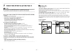
INSTALLATION OF R32 OR R410A 

REFRIGERANT AIR CONDITIONER

This PMV Kit adopts the HFC refrigerant (R32 OR R410A) which does not deplete the ozone layer.

Be sure to read and follow the Installation Manuals for indoor and outdoor units for precautions regarding the 
characteristics of the refrigerant, the tools used, and the refrigerant piping. It is different from the conventional 
refrigerant (R22).

Refrigerant piping

• Piping material used for the conventional refrigerant cannot be used.
• Use copper pipe with 0.8 mm or more thickness for Dia.6.4, Dia.9.5, Dia.12.7 mm.
• Flare nut and flare works are also different from those of the conventional refrigerant.

Take out the flare nut attached to the unit of the air conditioner, and use it.

13-EN

14-EN

Summary of Contents for RBM-PMB0361U-E

Page 1: ...Installation Manual PMV Kit RBM PMV0361U E RBM PMV0901U E English R32 or R410A ...

Page 2: ...ant HFC R32 or R410A which does not destroy the ozone layer Be sure to check the refrigerant type for outdoor unit to be combined and then install it Accessory parts For other languages that do not appear in this Installation Manual please refer to the enclosed CD ROM Part name Q ty RBM Shape Usage PMV0361U E PMV0901U E Installation Manual 1 1 This manual Hand over to customers Connection cable Co...

Page 3: ...that the concentration of refrigerant leakage occur in the room does not exceed the critical level Install the air conditioner securely in a location where the base can sustain the weight adequately Perform the specified installation work to guard against an earthquake If the air conditioner is not installed appropriately accidents may occur due to the falling unit WARNING If refrigerant gas has l...

Page 4: ...s and comes in contact with fire or heating part it will create harmful gas and there is risk of fire WARNING CAUTION General Installation space area The installation of pipe work shall be kept to a minimum Pipe work shall be protected from physical damage The compliance with national gas regulations shall be observed The mechanical connections shall be accessible for maintenance purposes In cases...

Page 5: ... or ignition risks No Smoking signs shall be displayed 7 Ventilated area Ensure that the area is in the open or that it is adequately ventilated before breaking into the system or conducting any hot work A degree of ventilation shall continue during the period that the work is carried out The ventilation should safely disperse any released refrigerant and preferably expel it externally into the at...

Page 6: ...otential sources of ignition be used in the searching for or detection of refrigerant leaks A halide torch or any other detector using a naked flame shall not be used Electronic leak detectors may be used to detect refrigerant leaks but in the case of flammable refrigerants the sensitivity may not be adequate or may need re calibration Detection equipment shall be calibrated in a refrigerant free ...

Page 7: ...appropriate purging gas The system shall be leak tested on completion of charging but prior to commissioning A follow up leak test shall be carried out prior to leaving the site 17 Decommissioning Before carrying out this procedure it is essential that the technician is completely familiar with the equipment and all its details It is recommended good practice that all refrigerants are recovered sa...

Page 8: ...nition in the event of a refrigerant release Consult manufacturer if in doubt The recovered refrigerant shall be returned to the refrigerant supplier in the correct recovery cylinder and the relevant waste transfer note arranged Do not mix refrigerants in recovery units and especially not in cylinders If compressors or compressor oils are to be removed ensure that they have been evacuated to an ac...

Page 9: ...al Regulation Caution when installing the PMV Kit at a place with low background noise This PMV Kit has a built in pulse motor valve expansion valve generating refrigerant sounds during operation Thus avoid installing it in the following rooms with low background noise and install it in isolated spaces from a living space Room with low background noise bedrooms hospital rooms or hotel rooms Room w...

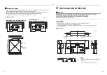
Page 10: ...OF PMV KIT WARNING Install the unit securely in the place to sufficiently withstand the weight of the unit If the foundation is not sturdy enough the unit may fall and cause personal injury Perform a specified installation work to guard against earthquake Improper installation may cause the unit to fall REQUIREMENT To prevent damage on the PMV Kit or personal injury follow the instructions below D...

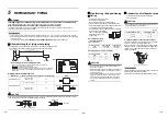
Page 11: ...nit and the outdoor unit Attached joint Attached joint Attached joint Liquid pipe Attached joint Seal pipe PMV Kit Pipe forming End positioning Flaring 1 Cut the pipe with a pipe cutter Remove burrs completely Remaining burrs may cause gas leakage 2 Insert a flare nut into the pipe and flare the pipe As the flaring sizes of R32 or R410A differ from those of refrigerant R22 the flare tools newly ma...

Page 12: ...e Using the attached heat insulating pipe perform heat insulating process securely for pipe connecting part of the PMV Kit without clearance Union PMV Kit Flare nut Heat insulating pipe Attached Binding band M Attached Heat insulator Indoor unit Refrigerant pipe PMV Kit Apply an extra heat insulation to the liquid pipe between the PMV Kit and the indoor unit depending on using environment Failure ...

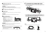
Page 13: ...sory Remove an existing PMV lead wire connecting to the connector CN82 on the P C board in the indoor unit and replace it with the PMV Kit connection wire approximately 11 m For details of installation see Work procedure 1 2 and 3 on the next page Work procedure 1 Applicable model High wall type MMK UP 1H series PMV Kit connection wiring method To comply with the EMC Electromagnetic Compatibility ...

Page 14: ...lamp filter Accessory Model name E04SR401938 Binding band M Lock securely with claws Incorrect wiring pattern Clamp filter Accessory Connection cable to PMV Kit 4 After turning off the power supply remove the terminal cover and the clamp base 5 Replace the PMV connector built in the indoor unit with the connection cable of PMV Kit The lock mechanism is provided at side of PMV connector Remove the ...

Page 15: ...e indoor unit side must be placed in the specified position as shown in the picture next page and then the PMV Kit connection cable must be routed appropriately 8 Fix the connection cable of PMV Kit with cord clamp for existing wiring NOTE Follow steps 6 7 and 8 so that the portions of the cable before and after each of the clamp filters including the one already installed in the electrical parts ...

Page 16: ...ts box cover of the indoor unit after power off and then process wiring work For details refer to the Installation Manual attached to the indoor unit 5 Replace the PMV connector built in the indoor unit with the connection cable of PMV Kit The lock mechanism is provided at side of PMV connector Remove the connector by releasing the lock mechanism 6 Be sure to install another clamp filter accessory...

Page 17: ...EB99835101 3 DH91307803 ...

Reviews: