background image

� 9 �

17-EN

18-EN

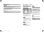
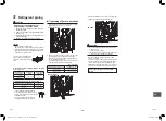
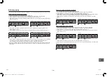
Obstacles in both front and rear of unit

Open above and to the right and left of the unit. 

The height of an obstacle in both the front and rear of 

the unit, should be lower than the height of the outdoor

unit.

Standard installation

1. Single unit installation

39.4” (1,000)  or more

5.9” (150)  or more

2. Serial installation of two or more units

39.4” (1,000)  or more

7.9” (200) 

or more

11.8” (300) or more

11.8” (300) 

or more

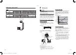
Serial installation in front and rear

Open above and to the right and left of the unit.

The height of an obstacle in both the front and rear 

of the unit, should be lower than the height of the 

outdoor unit.

Standard installation

39.4” 

(1,000) 

or more

78.7” 

(2,000) 

or more

59.1” 

(1,500) 

or more

11.8” 

(300) 

or more

7.9”

(200) 

or more


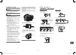
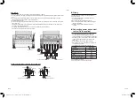
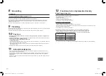
Installation of outdoor unit

 Before installation, check the strength and

  horizontalness of the base so that abnormal sounds

  do not emanate.

 According to the following base diagram, fix the base  

  firmly with the anchor bolts.

  (Anchor bolt, nut: 3/8” (M10) × 4 pairs)

Ø1.0” (25) 

Drain hole

13.0” (330)

2.4” (60)

3.5” (90)

3.5” (90)

23.6” (600)

4.3” (108)

12.1” (306)

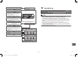
 As shown in the figure below, install the foundation

  and vibration-proof rubber pads to directly support

  the bottom surface of the fixing leg that is in contact

  with and underneath the bottom plate of the outdoor

 unit.

*  When installing the foundation for an outdoor unit

  with downward piping, consider the piping work.

Absorb vibration

with vibration proof

rubber pads

Fixing leg

Correct

Correct

Foundation

Foundation

Foundation

Bottom plate of

outdoor unit

Support the bottom surface of the fixing 

leg that is in contact with and underneath 

the bottom plate of the outdoor unit.

Incorrect

Do not support the 

outdoor unit only 

with the fixing leg.

If only the end of

the fixing leg is

supported, it may

deform.

Set the out margin of the anchor bolt to 0.6” (15 mm) 

or less.

0.6” (15 mm) or less

• When water is to be drained through the drain hose,

  attach the following drain connector and waterproof

  rubber cap, and use the drain hose (Inner dia.:

  16 mm) field supplied drain hose. Also seal the

  screws securely with silicone material, etc., to

  prevent water from leaking. Some conditions may

  cause dewing or dripping of water.

• When collectively draining discharged water

  completely, use a drain pan.

Drain connector

Base plate

Waterproof

rubber cap

Waterproof rubber cap

(2 pcs.)


For reference

If a heating operation is to be continuously performed

for a long time under the condition that the outdoor

temperature is 0°C or lower, draining defrosted water

may be difficult due to the bottom plate freezing,

resulting in trouble with the cabinet or fan.

It is recommended to procure an anti-freeze heater

locally in order to safely install the air conditioner.

For details, contact the dealer.

Drain connector

1131701101-00_S01_297x210_60p_S_p70_220426.indd   9

26/4/2565   11:41:09

Summary of Contents for RAV-SP122AT2P-UL

Page 1: ...al Outdoor Unit Model name Heat Pump Model RAV SP122AT2P UL RAV SP182AT2P UL 1131701101 For commercial use Pour usage commercial Para uso comercial English Installation Manual 1 1131701101 00_S01_297x210_60p_S_p70_220426 indd 1 26 4 2565 11 41 08 ...

Page 2: ... 14 13 Troubleshooting 17 14 Appendix 17 15 Specifications 18 1 EN 2 EN Original instruction Please read this Installation Manual carefully before installing the Air Conditioner This Manual describes the installation method of the outdoor unit For installation of the indoor unit refer the Installation Manual attached to the indoor unit ADOPTION OF NEW REFRIGERANT This Air Conditioner uses R410A an...

Page 3: ... Qualified service person The qualified service person is a person who installs repairs maintains relocates and removes the air conditioners made by Manufacturer He or she has been trained to install repair maintain relocate and remove the air conditioners made by Manufacturer or alternatively he or she has been instructed in such operations by an individual or individuals who have been trained an...

Page 4: ...equipment observe precautions in the literature and on tags stickers and labels attached to the equipment Follow all safety codes Wear safety glasses and work gloves Keep quenching cloth and fire extinguisher nearby when brazing Use care in handling rigging and setting bulky equipment Read these instructions thoroughly and follow all warnings or cautions included in literature and attached to the ...

Page 5: ...ty guards or by by passing any of the safety interlock switches Do not touch the intake or aluminium fins of the outdoor unit Doing so may result in injury Tighten the flare nut with a torque wrench in the specified manner Excessive tightening of the flare nut may cause a crack in the flare nut after a long period which may result in refrigerant leakage Install the air conditioner securely in a lo...

Page 6: ...gerant pipe Disconnecting the refrigerant pipe with the service valve left open and with the compressor still operating will cause air etc to be sucked in raising the pressure inside the refrigeration cycle to an abnormally high level and possibly resulting in rupturing injury etc WARNING After installation work make sure below before operation Connection pipes are connected properly and no leakag...

Page 7: ...unit and installation tools are different from those of the conventional refrigerant units Accordingly special tools are required for the new refrigerant R410A units For connecting pipes use new and clean piping materials with high pressure fittings made for R410A only so that water and or dust does not enter Required Tools Equipment and precautions for use Prepare the tools and equipment listed i...

Page 8: ...ves on the gas and liquid sides 2 Pressurize the pipe with nitrogen gas charged from the service port to the design pressure 4 15 MPa to conduct an leakage test 3 Check for gas leaks using a leak tester for the HFC refrigerant 4 After the leakage test is completed evacuate the nitrogen gas Evacuation To evacuate system use a vacuum pump Do not use refrigerant charged in the outdoor unit for evacua...

Page 9: ...ere the operating noise of the outdoor unit is transmitted When the outdoor unit is installed in an elevated position be sure to secure its feet A location in which drain water poses any problems When an outdoor unit is installed in a location that is always exposed to strong winds like a coast or on the high stories of a building one of the following is recommended Install the unit so that its di...

Page 10: ...oundation for an outdoor unit with downward piping consider the piping work Absorb vibration with vibration proof rubber pads Fixing leg Correct Correct Foundation Foundation Foundation Bottom plate of outdoor unit Support the bottom surface of the fixing leg that is in contact with and underneath the bottom plate of the outdoor unit Incorrect Do not support the outdoor unit only with the fixing l...

Page 11: ...eck for gas leaks at connected points Tightening of flare connections 1 Align the centers of the flare connections and fully tighten the flare nuts with your fingers Valve at liquid side 2 Use two wrenches to loosen or tighten the flare nut on the gas service valve as shown in the figure Use only one wrench to loosen or tighten the flare not on the liquid service valve The final tightening with a ...

Page 12: ... Unit 500 microns Low side valve High side valve Vacuum pump Packed valve at gas side Charge port Valve core Setting pin Indoor Unit Service Valve High Side Refrigerant Low Side Charge hose Charge hose Deep Vacuum Method The deep vacuum method requires a vacuum pump capable of pulling a vacuum of 500 microns and a vacuum gage capable of accurately measuring this vacuum depth The deep vacuum method...

Page 13: ...ntil and the gauge of manifold dropped into the range of 0 5 0 kgf cm2 8 Use the Hexagon wrench to turning the valve rod of Gas side fully close And turn off the Air Conditioner system immediately thereafter 9 Remove the gauge manifold from the service port of the packed valve 10 Securely tighten the valve rod cap to the both service valves CAUTION Should be check the compressor operating conditio...

Page 14: ...rconnections should be minimum 16 AWG Stripping length power cord and connecting wire Ground wire in mm Ground wire System interconnection wire Power supply wire How to wire 1 Remove the terminal cover by taking off the mounting screw 1 piece 2 Connect the power supply wires and system interconnection wires to the terminal block of the electrical control box 3 Tighten the screws of the terminal bl...

Page 15: ...due to the high frequency wave generated by the frequency converter inverter in the outdoor unit If you touch the charged outdoor unit without a grounding wire you may experience an electric shock 9 Finishing After the refrigerant pipe inter unit wires and drain pipe have been connected make sure they are supported and fixed in place for the entire length Keep the power wires and system interconne...

Page 16: ... the course of this operation hold down SW01 and SW02 simultaneously for at least 5 seconds to return to the initial status and then repeat the steps for recovering the refrigerant 29 EN 30 EN Refrigerant recovery When recovering the refrigerant in situations such as when relocating an indoor unit or outdoor unit the recovery operation can be performed by operating the SW01 and SW02 switches on th...

Page 17: ...indicated when step 4 is taken D800 D801 D802 D803 D804 D805 ON OFF Slow flashing EN 31 EN 32 EN Existing piping The following settings are required when using a pipe Ø3 4 19 1 mm as the existing piping at the gas pipe side Steps taken to support existing piping 1 Set the circuit breaker to the ON position to turn on the power 2 Check that the LED displays are placed in their initial status If not...

Page 18: ...he specified Pipe diameter and thickness be sure to use new pipes for the refrigerant piping works The operating pressure of R410A is high 1 6 times that of R22 and R407C If there is a scratch or dent on the pipe or a thinner pipe is used the pressure strength may be inadequate which may cause the pipe to break in the worst case Pipe diameter and thickness in mm Pipe outer diameter 1 4 6 4 3 8 9 5...

Page 19: ...e the enclosed refrigerant label adjacent to the charging and or recovering location 2 Clearly write the charged refrigerant quantity on the refrigerant label using indelible ink Then place the included transparent protective sheet over the label to prevent the writing from rubbing off 3 Prevent emission of the contained fluorinated greenhouse gas Ensure that the fluorinated greenhouse gas is neve...

Page 20: ...s almost non existent If a conditioner system is to be installed in a small room select a suitable model and installation procedure so that if the refrigerant accidentally leaks out its concentration does not reach the limit and in the event of an emergency measures can be made before injury can occur In a room where the concentration may exceed the limit create an opening with adjacent rooms or i...

Page 21: ...1131701101 1131701101 00_S01_297x210_60p_S_p70_220426 indd 59 26 4 2565 11 41 31 ...

Reviews: