– 17 –
Concealed Duct High Static Pressure
Installation Manual
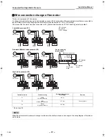
Wire connection change of fan motor
This duct is composed of 3 fan motors.
To change external static pressure by duct resistance, connect the 3 connectors of the orange lead wires that are connected to
the underside of the fan tap changing terminal block to the same number (F1, F2 or F3) terminal.
The wires of the fan motor has been connected to (F2) [External static pressure 137Pa (14mmAq)] as factory default.
* Do not use F4.
NOTE
When the external static pressure is changed, write down the static pressure once change in the wiring diagram of the indoor
unit is made.
Terminal block No.
Fan motor wiring
External static pressure
Pa (mmAq)
Remarks
F1
Yellow
Low static pressure
69 (7)
F2
Blue
Middle static pressure
137 (14)
Factory default
F3
Orange
High static pressure
196 (20)
F
1
F
2
F
3
F
4
FM
F
1
F
2
F
3
F
4
FM
F
1
F
2
F
3
F
4
FM
Low static pressure (F1)
BLU
ORG
YEL
ORG
YEL: Yellow
BLU: Blue
ORG: Orange
ORG
ORG
BL
U
ORG
YE
L
BL
U
ORG
YE
L
Fan motor
Fan motor
Fan motor
FAN3
FAN2
FAN1
F
1
F
2
F
3
F
4
FM
F
1
F
2
F
3
F
4
FM
F
1
F
2
F
3
F
4
FM
Standard (Middle) static pressure (F2)
BL
U
ORG
YE
L
ORG
OR
G
ORG
BLU
ORG
YEL
BL
U
OR
G
YE
L
Electrical control box
Fan tap changing
terminal block
Fan motor
Fan motor
Fan motor
2P terminal
block
3P terminal
block
4P terminal
block
Control
P.C. board
FAN3
FAN2
FAN1
F
1
F
2
F
3
F
4
FM
F
1
F
2
F
3
F
4
FM
F
1
F
2
F
3
F
4
FM
High static pressure (F3)
BL
U
OR
G
YE
L
ORG
ORG
ORG
BL
U
ORG
YEL
BL
U
ORG
YE
L
Fan motor
Fan motor
Fan motor
FAN3
FAN2
FAN1
17-EN
+00EH99871101.book Page 17 Friday, April 23, 2010 6:05 PM
Summary of Contents for RAV-SM2242DT-E
Page 202: ...EH99871101 ...

