background image

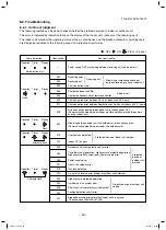
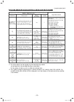
– 45 –

FILE NO. SVM-13072

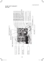
7-2. Outdoor Print Circuit Board

RAV-SM564AT

*

P

*

, SM804AT

*

P

*

<MCC-1645>

Lead

 for grounding 

(Black)

Lead and connector

 for 

Reactor

CN

300  

:  

Fan motor conector

Lead and connector

 for 

Reactor

J

800 

803  

:  

Jumper

 for model 

F

0

3

 : 

 3

.15

fuse

L-phase power supply lead (Black)

N-phase power supply lead (White)

Serial

 lead (Orange)

F

0

1


:  

25

A fuse

CN

704  

:  

4

-way valve connector

CN

500  

:  

Compressor

 case thermo connector 

CN

501  

:  

High pressure

 switch

 connector 

CN

806  

:  

Optional connector

CN

602  

:  

TO sensor connector

CN

603  

:  

TS sensor connector

CN

600  

:  

TE sensor connector

CN

601  

:  

TD sensor connector

CN

604  

:  

TL sensor connector

CN

700  

:  

PMV connector

F

0

2

 :  

3

.15

A fuse

C09

, C10

Electric capacitor

CN

807  

:  

Connector for display 

Compressor

 leads

(Red, White, Black)

SVM-13072.indb   45

SVM-13072.indb   45

11/01/13   1:53 PM

11/01/13   1:53 PM

Summary of Contents for RAV-SM1104ATJP-E

Page 1: ... SM564ATP E TR RAV SM804ATP E TR RAV SM1104ATP E TR RAV SM1404ATP E TR RAV SM564ATJP E RAV SM804ATJP E RAV SM1104ATJP E RAV SM1404ATJP E AIR CONDITIONER SPLIT TYPE FILE NO SVM 13072 SVM 13072 indb 1 SVM 13072 indb 1 11 01 13 1 53 PM 11 01 13 1 53 PM ...

Page 2: ...ne of Main Controls 40 7 2 Outdoor Print Circuit Board 45 8 TROUBLESHOOTING 47 8 1 Summary of Troubleshooting 47 8 2 Troubleshooting 49 8 3 Table Inspection of outdoor unit main parts 72 9 SETUP AT LOCAL SITE AND OTHERS 73 9 1 Calling of Error History 73 9 2 Group Control Operation 73 9 3 Outdoor Unit 75 9 4 Applicable Control of Outdoor Unit 84 10 ADDRESS SETUP 85 10 1 Address Setup Procedure 85 ...

Page 3: ...y acquainted with the knowledge related to this work s The qualified installer who is allowed to work at heights has been trained in matters relating to working at heights with the air conditioners made by Toshiba Carrier Corporation or alternatively he or she has been instructed in such matters by an individual or individuals who have been trained and is thus thoroughly acquainted with the knowle...

Page 4: ...ts Indications Illustrated marks and keep them Explanation of indications Indication DANGER WARNING CAUTION Explanation Indicates contents assumed that an imminent danger causing a death or serious injury of the repair engineers and the third parties when an incorrect work has been executed Indicates possibilities assumed that a danger causing a death or serious injury of the repair engineers the ...

Page 5: ...this panel CAUTION Do not touch the aluminum fins of the unit Doing so may result in injury CAUTION BURST HAZARD Open the service valves before the operation otherwise there might be the burst Description WARNING ELECTRICAL SHOCK HAZARD Disconnect all remote electric power supplies before servicing WARNING Moving parts Do not operate unit with grille removed Stop the unit before the servicing CAUT...

Page 6: ... to the Service Manual You may receive an electric shock if the voltage stored in the capacitors has not been sufficiently discharged Place a Work in progress sign near the circuit breaker while the installation maintenance repair or removal work is being carried out There is a danger of electric shocks if the circuit breaker is set to ON by mistake When checking the electric parts removing the co...

Page 7: ... stove etc be sure to put out fire before work otherwise the oil mixed with refrigerant gas may catch fire 2 Do not use a welder in the closed room When using it without ventilation carbon monoxide poisoning may be caused 3 Do not bring inflammables close to the refrigerant cycle otherwise fire of the welder may catch the inflammables WARNING General Check earth wires Prohibition of modification D...

Page 8: ...surely assemble the disassembled parts and connect and lead the removed wires as before Perform the work so that the cabinet or panel does not catch the inner wires If incorrect assembly or incorrect wire connection was done a disaster such as a leak or fire is caused at user s side After the work has finished be sure to use an insulation tester set 500V Megger to check the resistance is 1MΩ or mo...

Page 9: ...ng the pressure inside the refrigeration cycle to an abnormally high level and possibly resulting in reputing injury etc When the service panel of the outdoor unit is to be opened in order for the compressor or the area around this part to be repaired immediately after the air conditioner has been shut down set the circuit breaker to the OFF position and then wait at least 10 minutes before openin...

Page 10: ...ineering Director Toshiba Carrier UK Ltd Porsham Close Belliver Industrial Estate PLYMOUTH Devon PL6 7DB United Kingdom Authorized Hereby declares that the machinery described below Generic Denomination Air Conditioner Model type Commercial name Digital Inverter Series Air Conditioner Complies with the provisions of the Machinery Directive Directive 2006 42 EC and the regulations transposing into ...

Page 11: ...AV SM564ATJP E 40 RAV SM804ATP E 44 RAV SM804ATJP E 44 RAV SM1104ATP E 71 68 RAV SM1104ATJP E 71 68 RAV SM1404ATP E 71 68 RAV SM1404ATJP E 71 68 RAV SM564ATP TR 40 RAV SM804ATP TR 44 RAV SM1104ATP TR 71 68 RAV SM1404ATP TR 71 68 Under 70 dBA SVM 13072 indb 11 SVM 13072 indb 11 11 01 13 1 53 PM 11 01 13 1 53 PM ...

Page 12: ...are affected by impurities such as water oxide scales oil etc Use the clean pipes Be sure to brazing with flowing nitrogen gas Never use gas other than nitrogen gas 4 For the earth protection use a vacuum pump for air purge 5 R410A refrigerant is azeotropic mixture type refrigerant Therefore use liquid type to charge the refrigerant If using gas for charging composition of the refrigerant changes ...

Page 13: ...acuum pump by attaching vacuum pump adapter 7 Screwdriver h c n e r w y e k n o M r o r e n n a p S 8 h c n e r w e u q r o T 2 l l i r d e r o c e l o H 9 r e t t u c e p i P 3 m m 4 e d i s e t i s o p p O h c n e r w n o g a x e H 0 1 r e m a e R 4 e r u s a e m e p a T 1 1 r e d n e b e p i P 5 w a s l a t e M 2 1 l a i v l e v e L 6 Also prepare the following equipments for other installation...

Page 14: ...ector 20g m 21m to 30m 40g m 21m to 30m Height difference Outdoor lower m 30 30 Outdoor higher m 30 30 Outer dimension Height mm 550 550 Width mm 780 780 Depth mm 290 290 Appearance Silky shade Muncel 1Y8 5 0 5 Total weight kg 40 44 Heat exchanger Finned tube Fan unit Fan Propeller fan Standard air flow high m3 min 40 45 Motor W 43 43 Connecting pipe Gas side mm 12 7 15 9 Liquid side mm 6 4 9 5 So...

Page 15: ...o 50m 40g m 31m to 50m Height difference Outdoor lower m 30 30 Outdoor higher m 30 30 Outer dimension Height mm 890 890 Width mm 900 900 Depth mm 320 320 Appearance Silky shade Muncel 1Y8 5 0 5 Total weight kg 68 68 Heat exchanger Finned tube Fan unit Fan Propeller fan Standard air flow high m3 min 70 70 Motor W 100 100 Connecting pipe Gas side mm 15 9 15 9 Liquid side mm 9 5 9 5 Sound pressure le...

Page 16: ...tio Outdoor temp C Capacity ratio 0 2 4 6 8 10 12 14 0 10 20 30 40 50 60 70 80 90 100 SM56 SM80 0 2 4 6 8 10 12 14 16 0 20 40 60 80 100 120 SM56 SM80 50 55 60 65 70 75 80 85 90 95 100 105 110 30 31 32 33 34 35 36 37 38 39 40 41 42 43 44 45 46 SM80 SM56 0 10 20 30 40 50 60 70 80 90 100 110 120 14 12 10 8 6 4 2 0 2 4 6 8 10 1 2 Operation Characteristic Curve SVM 13072_001 050 indd 16 SVM 13072_001 0...

Page 17: ...9 40 41 42 43 44 45 46 SM110 SM140 0 10 20 30 40 50 60 70 80 90 100 110 120 14 12 10 8 6 4 2 0 2 4 6 8 10 Compressor speed rps Current A Compressor speed rps Current A Outdoor temp C Capacity ratio Outdoor temp C Capacity ratio g n i t a e H g n i l o o C g n i t a e H g n i l o o C RAV SM1104AT P SM1404AT P s Capacity variation ratio according to temperature s Operation Characteristic Curve SVM 1...

Page 18: ... 18 FILE NO SVM 13072 2 CONSTRUCTION VIEWS EXTERNAL VIEWS 2 1 RAV SM564AT P SM804AT P SVM 13072 indb 18 SVM 13072 indb 18 11 01 13 1 53 PM 11 01 13 1 53 PM ...

Page 19: ... 19 FILE NO SVM 13072 2 2 RAV SM1104AT P SM1404AT P SVM 13072 indb 19 SVM 13072 indb 19 11 01 13 1 53 PM 11 01 13 1 53 PM ...

Page 20: ...r diameter Ø C Inner diameter Ø D Inner diameter Ø D A B Model RBC TWP30E2 Liquid side Gas side TWP50E2 Liquid side Gas side A B C D 36 14 Ø9 5 Ø6 4 43 23 Ø15 9 Ø12 7 34 14 Ø9 5 Ø9 5 44 21 Ø15 9 Ø15 9 SVM 13072 indb 20 SVM 13072 indb 20 11 01 13 1 53 PM 11 01 13 1 53 PM ...

Page 21: ... Heating Cooling Indoor unit Refrigerant pipe at liquid side Outer dia ØB Refrigerant pipe at gas side Outer dia ØA Distributor Strainer incorporated Strainer Heating Cooling TCJ sensor TC sensor Air heat exchanger To outdoor unit To outdoor unit s Single type Combination of 1 indoor unit and 1 outdoor unit s Twin type Combination of 2 indoor units and 1 outdoor unit Indoor unit SM56 2 Branch pipe...

Page 22: ...ndoor Outdoor temp conditions DB WB C MPa kg cm2 G Discharge TD Suction TS Indoor heat exchanger TC Outdoor heat exchanger TE Pd Ps Pd Ps Indoor Outdoor Cooling Standard 3 11 0 96 31 7 9 8 80 17 13 42 63 HIGH 27 19 35 Overload 3 37 1 08 34 4 11 0 77 21 17 53 35 HIGH 32 24 46 Low load 1 90 0 70 19 4 7 1 48 7 5 30 50 LOW 18 15 5 5 Heating Standard 2 27 0 63 23 1 6 4 68 5 37 1 66 HIGH 20 7 6 Overload...

Page 23: ...door fan Indoor Outdoor temp conditions DB WB C MPa kg cm2 G Discharge TD Suction TS Indoor heat exchanger TC Outdoor heat exchanger TE Pd Ps Pd Ps Indoor Outdoor Cooling Standard 3 27 0 89 33 3 9 1 82 12 10 41 80 HIGH 27 19 35 Overload 3 63 1 26 37 0 10 2 80 19 18 51 53 HIGH 32 24 46 Low load 1 96 0 85 20 0 8 7 53 4 3 16 72 HIGH 18 15 5 5 Heating Standard 2 61 0 64 26 6 6 5 74 3 43 2 92 HIGH 20 7...

Page 24: ...ributor 4 way valve STF H0218 Ø25 L180 Ø25 L210 Rotary compressor DA330A2T 20M Accumulator 1800cc Heat exchanger Ø8 2 rows 40 steps FP1 3 flat fin R410A 2 8kg Cooling Heating Muffler PMV Pulse Motor Valve CAM BD25TCTH 1 P Pressure switch TŌ sensor RAV SM1104AT P SM1404AT P SVM 13072 indb 24 SVM 13072 indb 24 11 01 13 1 53 PM 11 01 13 1 53 PM ...

Page 25: ...5 15 RAV SM1404AT P Pressure Pipe surface temperature C Comp Hz Fan Temp MPa kg cm2 G Pd Ps Pd Ps TD TS TC TE In Out Cooling Standard 3 37 0 85 34 4 8 7 89 13 11 40 70 HIGH 27 19 35 Overload 3 65 1 07 37 2 10 9 80 16 18 54 53 HIGH 32 24 46 Low load 2 05 0 83 20 9 8 5 56 10 8 4 30 LOW 18 15 5 15 Heating Standard 2 79 0 63 28 4 6 4 79 3 45 2 67 HIGH 20 7 6 Overload 3 10 1 12 30 6 11 4 75 19 51 16 30...

Page 26: ... 26 FILE NO SVM 13072 4 WIRING DIAGRAM 4 1 RAV SM564AT P SM804AT P SVM 13072 indb 26 SVM 13072 indb 26 11 01 13 1 53 PM 11 01 13 1 53 PM ...

Page 27: ... 27 FILE NO SVM 13072 4 2 RAV SM1104AT P SM1404AT P SVM 13072 indb 27 SVM 13072 indb 27 11 01 13 1 53 PM 11 01 13 1 53 PM ...

Page 28: ...temp sensor TL sensor 50 kΩ at 25 C 16 Compressor thermo Protection CS 12AL OFF 125 4 C ON 90 5 C RAV SM1104AT P SM1404AT P No Parts name Type Specifications 1 Compressor DA330A2T 20M 3 phase 4P 3000W 2 Fan motor WDF 340 A100 1 Output 100 W 3 4 way valve coil STF H01AZ1724A1 4 PMV coil CAM MD12TF 18 5 High pressure SW ACB 4UB83W OFF 4 15MPa 6 Reactor CH 62 6mH 18 5A 7 P C board MCC 1648 8 Fuse Mou...

Page 29: ...sonal injury may be caused 5 After completion of installation work check to make sure that there is no refrigeration gas leakage If the refrigerant gas leaks into the room coming into contact with fire in the fan driven heater space heater etc a poisonous gas may occur 6 When an air conditioning system charged with a large volume of refrigerant is installed in a small room it is necessary to exerc...

Page 30: ...dust does not enter the pipe interior that no other oil other than lubricating oils used in the installed air conditioner is used and that refrigerant does not leak When using lubricating oils in the piping processing use such lubricating oils whose water content has been removed When stored be sure to seal the container with an airtight cap or any other cover 1 Flare Processing Procedures and Pre...

Page 31: ...tional flare tool R410A Clutch type Wing nut type 1 0 to 1 5 1 5 to 2 0 1 0 to 1 5 1 5 to 2 0 1 0 to 1 5 2 0 to 2 5 1 0 to 1 5 2 0 to 2 5 Conventional flare tool R22 Clutch type Wing nut type 0 5 to 1 0 1 0 to 1 5 0 5 to 1 0 1 0 to 1 5 0 5 to 1 0 1 5 to 2 0 0 5 to 1 0 1 5 to 2 0 Table 6 2 4 Flare and flare nut dimensions for R410A Table 6 2 5 Flare and flare nut dimensions for R22 Nominal diameter...

Page 32: ...may be made non removable When choosing the tightening torque comply with values designated by manufacturers Table 6 2 6 shows reference values NOTE When applying oil to the flare surface be sure to use oil designated by the manufacturer If any other oil is used the lubricating oils may deteriorate and cause the compressor to burn out Table 6 2 6 Tightening torque of flare for R410A Reference valu...

Page 33: ... closed position and turn off the vacuum pump s power switch Keep the status as it is for 1 to 2 minutes and ensure that the compound gauge s pointer does not return Set the refrigerant cylinder to the electronic balance connect the connecting hose to the cylinder and the connecting port of the electronic balance and charge liquid refrigerant 1 Never charge refrigerant exceeding the specified amou...

Page 34: ...posed of silver and copper It is used to join iron copper or copper alloy and is relatively expensive though it excels in solder ability 2 Phosphor bronze brazing filler Phosphor bronze brazing filler is generally used to join copper or copper alloy 3 Low temperature brazing filler Low temperature brazing filler is generally called solder and is an alloy of tin and lead Since it is weak in adhesiv...

Page 35: ...ich does not contain chlorine 3 When adding water to the flux use water which does not contain chlorine e g distilled water or ion exchange water 4 Remove the flux after brazing 6 5 3 Brazing As brazing work requires sophisticated techniques experiences based upon a theoretical knowledge it must be performed by a person qualified In order to prevent the oxide film from occurring in the pipe interi...

Page 36: ... will occur 8 Installation and removal of the air conditioner are repeated with temporary installation by lease and etc 9 In case that type of the refrigerator oil of the existing air conditioner is other than the following oil Mineral oil Suniso Freol S MS Synthetic oil alkyl benzene HAB Barrel freeze ester series PVE only of ether series s Winding insulation of the compressor may become inferior...

Page 37: ...VSOD V LQGLFDWHG ZKHQ VWHS LV WDNHQ GLVSOD V IRU H LVWLQJ SLSLQJ VHWWLQJV GLVSOD V LQGLFDWHG ZKHQ VWHS LV WDNHQ GLVSOD V LQGLFDWHG ZKHQ VWHS LV WDNHQ Q FDVH WKDW WKH JDV SLSH PP LV XVHG IRU WKH RXWGRRU XQLW RI 60 3 RU KLJKHU DV SLSH VL H RI RXU 5 PRGHO LV PP LVWLQJ SLSLQJ 7KH IROORZLQJ VHWWLQJV DUH UHTXLUHG ZKHQ XVLQJ D SLSH PP DV WKH H LVWLQJ SLSLQJ DW WKH JDV SLSH VLGH 6WHSV WDNHQ WR VXSSRUW H L...

Page 38: ...ll thickness equal to or larger than the following thickness s Never use any pipe with a wall thickness less than these thicknesses due to insufficient pressure capacity 1 2 3 4 ON 1 2 3 4 ON SW802 When shipped from factory When using existing pipe RAV SP804ATP s To use an existing Ø19 1 mm pipe set bit 3 of SW802 switch for existing pipe on the P C board of the outdoor unit to ON In this case the...

Page 39: ...rigerant and replenish the refrigerant Restrictions for the amount of additional charging a The amount of refrigerant additionally charged shall not exceed 10 of that specified If the situation is not solved with such amount recover the refrigerant completely and charge the specified amount b In case of slow leakage upon installation and the pipe connection length of not over 15m further tighten t...

Page 40: ...compressor life In a case of trouble on the compressor be sure to check there is no error in the resistance value an the refrigerating cycle of each sensor after repair and then start the operation 2 Discharge temperature release control 1 When the discharge temperature did not fall or the discharge temperature rapidly went up by PMV control this control lowers the compressor frequency It subdivid...

Page 41: ...n control 2 At the start time the fan is fixed for 60 seconds only with the maximum fan tap corresponded to the zone in the following table but it is controlled with TL sensor temperature after then 1 tap 20 sec Up to the maximum rotational frequency of each zone Rotational frequency hold 1 tap 20 sec Up to the minimum rotational frequency of each zone SM56 80 WE tap SM110 140 WD tap TL 55 C 38 C ...

Page 42: ...er 49 8Hz to 88 8Hz 88 8Hz or higher Max Max Max 10 C TO W7 W8 W9 5 C TO 10 C W9 WB WF 3 C TO 5 C WF WF WF 10 C TO 3 C WF WF WF TO 10 C WF WF WF TO error WF WF WF Temp range SM110 SM140 20 4 Hz or lower 20 4Hz to 45 0Hz 45 0Hz or higher Max Max Max 10 C TO W7 W8 W9 5 C TO 10 C W9 WB WE 3 C TO 5 C WE WE WE 10 C TO 3 C WE WE WE TO 10 C WE WE WE TO error WE WE WE 5 Coil heating control 1 This control...

Page 43: ...ed to restrain abnormal rising of high pressure by TL sensor in cooling operation and TC sensor in heating operation 2 When TL sensor in cooling operation or TC sensor in heating operation detects abnormal temperature of the stop zone stop the compressor and the error count becomes 1 3 When the compressor stopped with 2 the operation restarts from the point of the normal operation zone e point or ...

Page 44: ...TEO TE ToO TO 2 C continued for 20 seconds B zone When status of TEO TE 2 C continued for 20 seconds C zone When status of SM56 80 TE 25 C SM110 140 TE 18 C continued for 20 seconds D zone When compressor operation status with SM56 80 TE 13 C SM110 140 TE 2 C are added by d times 11 High pressure switch 1 When the high pressure switch operates the operation of the compressor is terminated 2 The co...

Page 45: ...lead White Serial lead Orange F01 25A fuse CN704 4 way valve connector CN500 Compressor case thermo connector CN501 High pressure switch connector CN806 Optional connector CN602 TO sensor connector CN603 TS sensor connector CN600 TE sensor connector CN601 TD sensor connector CN604 TL sensor connector CN700 PMV connector F02 3 15A fuse C09 C10 Electric capacitor CN807 Connector for display Compress...

Page 46: ...White Serial lead Gray F20 25A fuse CN700 4 way valve connector CN500 Compressor case thermo connector CN806 Optional connector CN602 TO sensor connector CN603 TE sensor connector CN605 TL sensor connector CN601 TD sensor connector CN604 TS sensor connector CN701 PMV connector C28 C29 C30 Electric capacitor Lead and connector for Reactor CN300 Fan motor conector Compressor leads Red White Black SV...

Page 47: ...ature release operation control is working in heating operation When outside low temperature operation control is working in cooling operation When defrost operation is being performed 4 ON OFF operation cannot be performed from remote controller When the control operation is being performed from outside remote side When automatic address is being set up When the power is turned on at the first ti...

Page 48: ...performed from remote controller When forced operation is being performed When the control operation is being performed from outside remote side When automatic address being set up When the test run is being performed by operation of the outdoor controller a Did you return the cabling to the initial positions b Are connecting cables between indoor unit and receiving unit correct 2 Troubleshooting ...

Page 49: ...error between indoor units Indoor power OFF Communication stop between indoor master and follower or between main and sub indoor twin Miswiring between indoor unit and outdoor unit or connection erorr Communication stop between indoor and outdoor units Overflow was detected Protective device of indoor unit worked Indoor DC fan error The following method can be done to check whether the problem occ...

Page 50: ...ror Discharge temp sensor TD error Temp sensor TE TS TL error Heat exchanger temp sensor TL error Outside air temp sensor TO error Suction temp sensor TS error Heat sink temp sensor TH error Miss mounting of temp sensor TE TS Indoor EEPROM error Outdoor EEPROM error Compressor break down Outdoor compressor system error Compressor lock Outdoor unit current detection circuit error Duplicated header ...

Page 51: ...ure 1 4 way only Unit C C C C rpm 100h 1h C Outdoor unit data CODE No 60 61 62 63 65 6A 6D 70 72 73 F1 Data name Outdoor heat exchanger Coil temperature TE Outside temperature TO Compressor discharge temperature TD Compressor suction temperature TS Heat sink temperature TH Operation current 1 10 Outdoor heat exchanger Coil temperature TL Compressor operation frequency Outdoor fan revolution freque...

Page 52: ...ROM error Heat sink temp sensor TH error 2 Outdoor unit Unset model type of service P C board 3 Outdoor Heat sink overheat error Gas leak detection or 4 way valve system error 1E P03 ALT Outdoor unit Discharge temp error Outdoor Error was detected by discharge temp release control 21 P04 ALT Outdoor unit High pressure SW system error Outdoor High pressure protection switch operated AF P05 ALT Powe...

Page 53: ...plicated indoor master units Indoor There are multiple master units in a group 99 L07 SIM There is group cable in individual indoor unit Indoor When even one group connection indoor unit exists in individual indoor unit 99 L08 SIM Unset indoor group address Indoor Indoor address group was unset 46 L09 SIM Unset indoor capacity Indoor Capacity of indoor unit was unset 66 L30 SIM Outside error input...

Page 54: ...ly operates Check P C board Indoor receiving Outdoor sending 1 Check whether remote controller connection Group Individual was changed or not after power supply turned on Finish of group construction Address check If group construction and address are not normal when the power has been turned on the mode automatically shifts to address setup mode Resetting of address 1 Set indoor capacity CODE No ...

Page 55: ...ected Displayed when error is detected Displayed when error is detected Displayed when error is detected Displayed when error is detected Displayed when error is detected Displayed when error is detected Displayed when error is detected Displayed when error is detected Displayed when error is detected Displayed when error is detected Judgmentandmeasures 1 Check discharge temp sensor TD 2 Check out...

Page 56: ...MV Pulse Motor Valve 5 Check broken pipe AC current detection circuit 1 Check refrigerating cycle Gas leak 2 Check PMV Pulse Motor Valve 3 Check discharge temp sensor TD 1 Check service valves are fully opened Gas side Liquid side 2 Check outdoor fan operation 3 Check motor error of outdoor fan 4 Check clogging of outdoor PMV 5 Check clogging of heat exchanger in indoor outdoor units 6 Short circu...

Page 57: ...center exists operation continues If center exists operation continues Stop Sub unit continues operation Continues By remote controller Continuation Stop According to each case Condition Displayed when error is detected Displayed when error is detected Displayed when error is detected Displayed when error is detected Displayed when error is detected Displayed when error is detected Judgment and me...

Page 58: ...Compressor break down H01 11 Compressor lock H02 12 Current detection circuit error H03 13 Case thermostat operation H04 14 Unset model type of P C board L10 15 Discharge temp error P03 16 High pressure SW system error P04 17 Power supply error P05 18 Heat sink overheat error P07 19 Gas leak detection P15 20 4 way valve inverse error P19 21 High pressure protective operation P20 22 Fan system erro...

Page 59: ... the following action As the memory is kept it is confirmed even after the power supply was turned off once Except outside air temp sensor TO error 1 Check D800 to D804 are turned off or rapid flashing and D805 is turned on When D800 to D804 are slowly flashing or D805 flashes push and hold SW01 and SW02 for 5 seconds or more simultaneously D800 to D804 will be turned off or rapid flashing and D80...

Page 60: ...ESS SETUP Correct wiring of connectors and terminal blocks Check outdoor P C board Defect Replace Correct wiring indoor outdoor control wires Is setting of group address of remote controller correct Are inner wiring and indoor outdoor control wires 1 2 3 correct Are wiring of terminal blocks 1 2 3 correct YES YES YES NO NO NO E04 60 SVM 13072 indb 60 SVM 13072 indb 60 11 01 13 1 53 PM 11 01 13 1 5...

Page 61: ... value of TE sensor correct Correct connector Sensor error Replace Check outdoor P C board Defect Replace YES NO Is SM56 80 CN604 SM110 140 CN605 connection correct Is resistance value of TL sensor correct Correct connector Sensor error Replace Check outdoor P C board Defect Replace YES NO Is CN601 connection correct Is resistance value of TD sensor correct Correct connector Sensor error Replace C...

Page 62: ...r error Replace Check outdoor P C board Defect Replace Is SM56 80 CN603 SM110 140 CN604 connection correct Is resistance value of TS sensor correct YES NO Check outdoor P C board Defect Replace Check outdoor P C board Defect Replace Correct connector Sensor error Replace Correct connector Sensor error Replace Correct sensor mounting Is mounting status of TE and TS sensors correct Is SM56 80 CN603 ...

Page 63: ...de Compressor side Reactor lead Power supply lead YES YES YES NO NO NO Check wire connection and correct it Correct power supply line Is compressor under correct condition Is there refrigerant stagnation Does PMV correctly operate Is power supply voltage correct 50 Hz AC 198 to 264 V 60 Hz AC 198 to 242 V Is wire connection correct Compressor lead P C board side Compressor side Reactor lead Power ...

Page 64: ... shortage Are CN500 connection and case thermostat correct Short each pins of CN500 Can compressor operate YES YES NO YES YES NO NO YES NO NO L10 Unset model type Only when service P C board is used Cut jumper line according to the explanation sheet packaged with the service P C board Check outdoor P C board Defect Replace Correct connector Sensor error Replace Repair defective position Replace de...

Page 65: ...cuit Parts check Defective Replace Elimination of blocking element Check outdoor PC board Defective Replace Wiring check Correct Open service valve fully Repair defective position Overcharge of refrigerant Clogging Pipe breakage Abnormal overload YES NO S E Y YES YES YES NO NO YES NO NO NO YES NO Are resistance value of TC and TCJ sensor correct Are connections of connectors capacitors and fan mot...

Page 66: ...g of screws Does anything block the ventilation around the heat sink Does anything block air flow from the fan Is the power device on P C board tightly screwed Are radiation grease properly applied Open service valve fully Correct and replace piping Correct connector Sensor error Replace Check outdoor P C board Defect Replace Correct defective position Replace defective part Repair defective posit...

Page 67: ... on When D800 to D804 flash slowly or D805 flashes push and hold SW01 and SW02 for 5 seconds or more simultaneously In the result D800 to D804 are turned off or rapid flashing and D805 changes from flashing to lighting 2 Push and hold SW01 for 5 seconds or more D804 changes to slow flashing 3 Push SW01 several time and stop it at LED display of the following Self preservation valve operation Self ...

Page 68: ...of indoor TC and TCJ sensors correct Replace sensor Check the same items as P22 error Check overcharge of refrigerant clogging of cycle broken pipe abnormal overload etc Defect Correct defective position Check overcharge of refrigerant clogging of cycle broken pipe abnormal overload etc Defect Correct defective position Eliminate interfering element Eliminate interfering element Heating season Hea...

Page 69: ... 5 Push and hold SW02 for 5 seconds or more As a result D804 changes to slow flashing D805 changes to lighting and the fan rotates 6 The fan stops when pushing long SW01 and SW02 for 5 seconds or more simultaneously or when 2 minutes passed If lost tracking on the operation push and hold SW01 and SW02 for 5 seconds or more simultaneously to return to the item 1 Outdoor fan single operation D800 D8...

Page 70: ...the unit automatically restarts and error is not determined A code may appear when an open phase of compressor coming out of wires or power relay trouble occurred Correct wiring Replace outdoor P C board YES NO Does the same error occur in operation without compressor lead Check compressor Layer short etc Defect Replace Are connections of compressor lead and reactor lead correct Check referring to...

Page 71: ...2 5 375 3 312 3 451 3 594 2 236 2 343 2 454 1 540 1 623 1 709 1 082 1 146 1 213 0 7740 0 8237 0 8761 0 5634 0 6023 0 6434 Temperature C 0 10 20 25 30 40 50 60 70 80 90 100 Resistance value kΩ Ω Ω Ω Ω Minimum value Standard value Maximum value 150 5 161 3 172 7 92 76 99 05 105 6 58 61 62 36 66 26 47 01 49 93 52 97 37 93 40 22 42 59 25 12 26 55 28 03 17 00 17 92 18 86 11 74 12 34 12 95 8 269 8 668 9...

Page 72: ... 20 C Red White Black 3 Compressor Model DA330A2T 20M Measure the resistance value of each winding by using the tester Position Resistance value Red White 0 37 Ω White Black Black Red Under 20 C Red White Black 4 Outdoor fan motor Model WDF 340 A100 1 Measure the resistance value of each winding by using the tester Position Resistance value Red White 17 3 1 7 Ω White Black Black Red Under 20 C Red...

Page 73: ...EMP CL FAN SAVE A A SWING FIX VENT MODE ON OFF UNIT LOUVER T Contents The error contents in the past can be called Procedure 1 Push SET TEST buttons simultaneously for 4 seconds or more to call the service check mode Service Check goes on the CODE No is displayed and then the content of the latest alarm is displayed The number and error contents of the indoor unit in which an error oc curred are d...

Page 74: ... is available Approx 50 seconds after power ON Regular communication between indoor units Every 30 seconds Master Follower Regular communication on the identical pipe every 30 seconds Twin Master Follower When the above status changes immediately communicates Repetition s The unit without power feed waits entirely Waiting status is released by system start s Reboot when power is fed on the way 3 m...

Page 75: ...s and then stop it at the point where LED display D800 to D804 is indicated as the following table ON OFF Rapid flashing 5 times second 5 Push SW02 so that D805 flashes rapidly 6 Push and hold SW02 for 5 seconds or more The forced cooling operation starts if D804 flashes slowly and D805 is turned on Max 10 minutes 7 After operation for 3 minutes or more close the valve at liquid side 8 After recov...

Page 76: ... seconds or more D804 changes to slow flashing 3 Push SW01 several times and then stop it at the point where LED display D800 to D804 to be checked If the setting became valid D804 and D805 flash rapidly When the setup was invalid D804 flashes rapidly and D805 goes off 4 Push SW01 and SW02 for 5 seconds or more simultaneously to return LED display to the initial status D800 D801 D802 D803 D804 D80...

Page 77: ...e control default Normal The heating only cooling only mode can be selected by the sub P C board of outdoor unit Sub P C P C board board selection mode setting Normal AUTO COOL DRY HEAT FAN ONLY or can be selected Cooling only COOL DRY FAN ONLY or can be selected 䞉The remote controller display becomes AUTO COOL Dry HEAT and FAN ONLY according to the connection and the indoor unit even if it sets f...

Page 78: ...ing 5 times sec Fig 1 䕻 Slow flashing 1 time sec D800 D801 D802 D803 D804 D805 䖃 or 䖂 䖃 or 䖂 䖃 or 䖂 䖃 or 䖂 䖃 or 䖂 䕿 OFF or Rapid flashing OFF or Rapid flashing OFF or Rapid flashing OFF or Rapid flashing OFF or Rapid flashing ON Fig 2 D800 D801 D802 D803 D804 D805 䕿 䖃 䖃 䖃 䕻 䖃 ON OFF OFF OFF Slow flashing OFF Fig 3 D800 D801 D802 D803 D804 D805 䕿 䕿 䖃 䖃 䖂 䖃 ON ON OFF OFF Rapid flashing OFF 䕿 䕿 䕿 䕿 䖂...

Page 79: ...flashing Rapid flashing 䕿 䕿 䕿 䕿 䖂 䖂 ON ON ON ON Rapid flashing Rapid flashing Fig 7 D800 D801 D802 D803 D804 D805 䕿 䕿 䖃 䖃 䖂 䖃 ON ON OFF OFF Rapid flashing OFF 䕿 䕿 䕿 䕿 䖂 䖃 ON ON ON ON Rapid flashing OFF Fig 8 D800 D801 D802 D803 D804 D805 䕿 䕿 䖃 䖃 䕻 䖃 ON ON OFF OFF Slow flashing OFF 䕿 䕿 䕿 䕿 䕻 䖃 ON ON ON ON Slow flashing OFF Selection mode Procedure 2 LED display Cooling only Heating only Cooling onl...

Page 80: ...nt value which flows to the outdoor unit is displayed D800 D801 D802 D803 D804 D805 Compressor operation frequency display The operation frequency of the compressor is displayed D800 D801 D802 D803 D804 D805 PMV opening display The opening of PMV Electronic expansion valve is displayed D800 D801 D802 D803 D804 D805 Indoor suction temperature sensor TA display The detected value of the indoor sucti...

Page 81: ...ction circuit error Power supply error Heat sink overheat error Gas leak detection 4 way valve reversal error High pressure protective operation Fan system error Driving element short circuit Position detection circuit error Others No determination F04 F06 F07 F08 F12 F13 F15 F31 H01 H02 L10 P03 P04 H03 P05 P07 P15 P19 P20 P22 P26 P29 L31 D800 D801 D802 D803 D804 D805 LED display Error name Normal...

Page 82: ...25 30 35 40 45 50 55 60 65 70 75 80 85 90 95 100 105 110 115 120 or more Sensor error 0 1 2 3 4 5 6 7 8 9 10 11 12 13 14 15 16 17 18 19 20 21 22 23 24 25 26 27 28 29 30 31 or more 0 5 10 15 20 25 30 35 40 45 50 55 60 65 70 75 80 85 90 95 100 105 110 115 120 125 130 135 140 145 150 155 or more 0 19 20 39 40 59 60 79 80 99 100 119 120 139 140 159 160 179 180 199 200 219 220 239 240 259 260 279 280 2...

Page 83: ...00 D801 D802 D803 D804 Fan motor forced operation Operate the fan motor forcedly Execute the following item 6 or the control returns to normal operation after 2 minutes Refer Note 1 ON OFF Rapid flashing 5 times second Note 1 Although these special operations are available even operating time basically carry out these operations while the machine stops If carrying out these operations the pressure...

Page 84: ...ut The capacity save is switched to 3 stages 75 50 and operation stop 2 Night operation Sound reduction Input a timer on the market Arranged at site The capacity is lowered regardless of load and the operation noise is reduced until 45dB However the normal control is carried out if the outside temperature TO sensor value is 40 C or more 3 Compressor operation output When the compressor drives turn...

Page 85: ...h indoor unit respectively in the group operation even if multiple refrigerant lines are provided the automatic address setup completes with power ON of the outdoor unit The operation of the remote controller is not accepted while automatic address works Approx 4 to 5 minutes s When the following addresses are not stored in the neutral memory IC503 on the indoor P C board a test run operation cann...

Page 86: ...entative unit Master Twin This unit communicates with the indoor unit follower which serial communicates with the outdoor units and sends receives signal Command from compressor to from the outdoor units as the representative of the cycle control in the indoor units of the identical line ad dress within the minimum unit which configures one of the refrigerating cycles of Twin Follower unit Subordi...

Page 87: ... identical line address indoor outdoor serial and then finally controls the outdoor compressor matching with its own thermo status The header unit sends this command information to the follower unit s Follower unit The follower unit receives the indoor unit data from the header With identical line address indoor outdoor serial and then performs the thermo operation synchronized with the header uni...

Page 88: ...urce power supply Automatic completion 3 Multiple groups operation 1 Single 2 Twin 2 1 Single Twin 1 1 1 2 2 1 Sub Header 1 1 Sub Header 3 1 Master Header 8 1 Sub Header 2 1 Sub Header 1 1 Sub Header 2 3 Master Follower 1 1 Individual Master Header Max 8 units 1 2 Master Header 1 1 1 2 1 1 Sub Follower Change is necessary Manually change addresses of the multiple follower units simultaneously from...

Page 89: ...e Indoor Outdoor connecting wires Outdoor side A B 1 1 L N 2 2 3 3 Power supply Remote controller Remote controller wiring Indoor side Indoor Outdoor connecting wires Outdoor side Example of 2 lines cabling Real line Cabling Broken line Refrigerant pipe For the above example perform setting by connecting singly the wired remote controller without remote controller inter unit cable Group address In...

Page 90: ... display goes on 11 Push TEST button Setup completes The status returns to the usual stop status 10 5 Confirmation of Indoor Unit No Position 1 To know the indoor unit addresses though position of the indoor unit body is recognized s In case of individual operation Wired remote controller indoor unit 1 1 Follow to the procedure during operation Procedure 1 Push ON OFF button if the unit stops 2 Pu...

Page 91: ... defective position or apply the rust resisting paint if necessary If an indoor unit operates for approx 8 hours or more per day usually it is necessary to clean the indoor outdoor units once three months at least These cleaning and maintenance should be carried out by a qualified dealer Although the customer has to pay the charge for the maintenance the life of the unit can be prolonged Failure t...

Page 92: ...SM804AT P 2 Jumper wires Jumper wires J800 J803 Cut the jumper wires of the service board as instructed in the table below The jumper setting of J800 J803 differs from original supplied P C Board therefore be sure to configure the jumpers as in the table below If the model is not specified the equipment will not operate Jumper wires J804 J805 Set the jumper wires J804 J805 of the service board to ...

Page 93: ...AT P RAV SM1404AT P Guide Hook Guide Hook Front side Back side Front side Back side Guide Hook Guide Hook 1 LED side of P C Board MCC 1646 shall be inserted to hook along the guide of mold 2 Switch side of P C Board MCC 1646 shall be pressed to hook along guide of mold 3 After assembly push SW01 and SW02 to check that switches can be click sound or feeling of click 93 SVM 13072 indb 93 SVM 13072 i...

Page 94: ... P 2 Jumper wires J800 J803 Cut the jumper wires of the service board as instructed in the table below The jumper setting of J800 J803 differs from original supplied P C Board therefore be sure to configure the jumpers as in the table below If the model is not specified the equipment will not operate Jumper wires J804 Set the jumper wire J804 of the service board to the same as settings of the P C...

Page 95: ...o the outdoor unit For the refrigerant recovery work during reinstallation of repair work be sure to use the refrigerant recovery unit Recovery of refrigerant to the outdoor unit is unavailable otherwise a serious accident such as explosion or injury may be caused 12 HOW TO EXCHANGE COMPRESSOR 12 1 Exchanging Procedure of Compressor Outline 12 2 Exchange of Compressor For exchange of compressors r...

Page 96: ...ws remove the upper cabinet pulling it upward 2 Attachment 1 Attach the waterproof cover CAUTION Be sure to attach a waterproof cover If it is not attached there is a possibility that water enters inside of the outdoor unit 2 Attach the upper cabinet ST1T Ø4 8L 5 pcs s Hook the rear side of the upper cabinet to claw of the rear cabinet and then put it on the front cabinet 3 Perform cabling of conn...

Page 97: ...slab ST1T Ø4 8 3 pcs 5 Remove the screw between front cabinet and motor base ST1T Ø4 8 2 pcs s EFT SIDE OF FRONT PANEL IS INSERTED INTO side cabinet left Remove by pulling the upper part 2 How to install 1 Insert front panel s hook into side cabinet left 2 Insert side cabinet left s hook into front cabinet s corner hole 3 Insert the removed screws to their positions Motor base Front cabinet Corner...

Page 98: ...ook Cover plate assembly Screw Never disassemble the inverter for 1minute after power has been turned off because an electric shock may be caused 3 Perform 1 of 2 4 Take off screw between side cabinet right and inverter box wiring gate side ST1T Ø4 8 2 pcs 5 Take off screw between partition plate and inverter box ST1T Ø4 8 1 pc 6 Remove each lead wire type from holder of inverter upper part 7 Pull...

Page 99: ...ESSOR 3P Relay connector white Warning 1 Reactor 2P Relay connector white Outdoor fan 3P white Warning 1 4 directional valve 3P yellow Warning 1 PMV coil 6P white Warning 1 TD sensor 3P white TS sensor 3P white Warning 1 TE sensor 2P white Warning 1 TL sensor 2P white Warning 1 TO sensor 2P white ASE THERMO 0 BLUE Warning 1 High pressure switch 3P green Warning 1 Warning 1 Please remove housing pa...

Page 100: ...screws that connect inverter box and P C board base And then remove inverter box from base P C board base Warning 2 Remove P C board base s hook Hook 1 2 3 4 hold P C board base pull inverter box up 4 Remove control board frame from PC board base Remove while heat sink is still attached to control board frame Warning 2 Remove PC board base s hook 4 places hold heat sink pull up 5 Take off 2 screws...

Page 101: ...ixing the fan motor and the propeller s Turning it clockwise the flange nut can be loosened To tighten the flange nut turn counterclockwise 3 Remove the propeller fan 4 Disconnect the connector for fan motor from the inverter 5 Take off the fixing screws 3 pcs holding by hands so that the fan motor does not fall NOTE Tighten the flange nut with torque 4 9Nm 50kgf cm Remarks 3 Take off fixed screw ...

Page 102: ...T Ø4 8L 8 Take off the fixing screws of the valve clamping plate to the bottom plate ST1T Ø4 8L 2 pcs 9 Pull upward he refrigerating cycle 10 Take off nut fixing the compressor to the bottom place CAUTION When reconnecting the lead wires to the compressor terminals after replacement of the compressor be sure to caulk the Faston terminal without loosening 1 Perform works of item 1 of 1 2 3 and Rema...

Page 103: ...wn so that fan guard side directs downward CAUTION Perform works on a corrugated cardboard cloth etc to prevent flaw on the product 3 Remove the hooking claws by pushing with minus screwdriver along with the arrow mark in the right figure and remove the fan guard 2 Attachment 1 Insert claws of the fan guard in the hole of the front cabinet Push the hooking claws 10 positions with hands and then fi...

Page 104: ...xagonal screw Ø4 10 5 pcs In this time insert the fin guard of rear side between the top plate and the heat exchanger Rear side 2 Connect the power supply wire and the indoor outdoor connecting wire to the terminal and fix it with cord clamp CAUTION Using bundling band on the market be sure to fix the power wire and indoor outdoor connecting wire along the crossover pipe so that they do not come t...

Page 105: ...rge port cabinet and the fin guard Hexagonal screw Ø4 10 2 pcs Remarks Side cabinet 3 1 Detachment 1 Carry out work of 1 of 1 2 Remove screws which fix the inverter assembly and the side cabinet ST1T Ø4 8 2 pcs 3 Remove screws of the side cabinet and the valve fixing plate ST1T Ø4 8 2 pcs 4 Remove screws of the side cabinet and the pipe panel Rear Hexagonal screw Ø4 10 2 pcs 5 Remove screws of the...

Page 106: ...heet in advance to adhere to the heat sink makes easy the work Remarks 2 Take off screws of cover inverter ST1T Ø4 10L 2 pcs 3 Remove the connectors connected to the control P C board Indoor power supply temperature sensors PMV coil 4 way valve coil compressor case thermo fan motor hight pressure switch display P C board Unlock the lock of the housing part and then remove the connectors 4 Remove c...

Page 107: ...f 1 and 3 2 Remove the relay connector connected to the control P C board Remarks Screws 3 Remove each reactor Truss B tight screw Ø4 6 2 pcs each 4 Attach a new reactor Reactor relay connector Connected to lead wire White at P C board side 107 SVM 13072 indb 107 SVM 13072 indb 107 11 01 13 1 53 PM 11 01 13 1 53 PM ...

Page 108: ...r not to put the fan motor lead into contact with the propeller fan Attach the fan motor lead fixing rubber to the partition plate so that projection directs to the refrigerating cycle side Be sure that the rector body does not come to contact with the fan motor lead Be sure to bind the removed bundling band with the bundling band on the market CAUTION Use the metal band of the motor base to fix t...

Page 109: ...d the accumulator Hexagonal screw Ø4 10 1 pc Cut off the bundling band for the dis charge pipe and the suction pipe and then remove each sensor and coil lead of PMV 6 Remove the soundproof plate Upper side outer winding inner winding 7 Remove terminal cover from the compressor and then remove the compressor lead and also the compressor case thermo 8 Remove TD sensor fixed to the discharge pipe 9 R...

Page 110: ...icient care CAUTION Note so that the flame does not catch the 4 way valve and PMV An operation may become an error 11 Pull off the discharge pipe and the suction pipe of the refrigerating cycle upward 12 Remove the compressor bolts which fix the compressor to the bottom plate 3 pcs 13 Pull out the compressor toward you X CAUTIONX The weight of the compressor is 15kg or more so handle it by 2 worke...

Page 111: ...and each sensor TL TO TE TD TS sensors PMV coil lead Pipe cover bundling band each sensor TL TO TE TD sensors PMV coil lead Bundling band each sensor TL TO TE sensors Suction pipe PMV coil lead Fix the removed each sensor and PMV coil lead wire to the discharge pipe and the suction pipe with the bundling band via the pipe cover In this time take note that each sensor and PMV coil lead wire do not ...

Page 112: ... of the outdoor unit Forced full opening method of PMV 4 Refrigerant charging 1 Add the quantity of refrigerant specified by the pipe length into the charge port of the valve Remarks 1 Detachment 1 Carry out works of 1 of 1 and 3 2 While pulling the coil upward and removing the spring which pinches the copper pipe remove the coil from PMV main body 2 Attachment 1 Match the spring to the copper pip...

Page 113: ...hen put on it so that the fan guard side directs downward 3 Remove the hooking claws 8 positions of the fan guard 2 Attachment 1 Push the hooking claws 8 positions with hands from the front side to fix the claws CAUTIONX Check that all the hooking claws are fixed at the specified positions Remarks Bell mouth Discharge port cabinet Fan guard Hooking claw 113 SVM 13072 indb 113 SVM 13072 indb 113 11...

Page 114: ... AND PARTS LIST 14 1 RAV SM564ATP E SM564ATJP E SM564ATP TR 22 10 11 12 13 16 30 15 29 14 1 6 27 32 33 35 3 5 37 36 4 7 8 17 18 19 20 31 23 24 25 26 28 9 2 21 34 114 SVM 13072 indb 114 SVM 13072 indb 114 11 01 13 1 54 PM 11 01 13 1 54 PM ...

Page 115: ...43T43491 ASM COND 1 1 18 43T43490 ASM COAT COND 1 19 43T21375 MOTOR FAN 1 1 1 20 43T20319 FAN PR PJ421 1 1 1 21 43T19329 GUARD FAN 1 1 1 22 43T19331 GUARD FIN 1 1 1 23 43T58306 REACTOR 2 2 2 24 43T60439 ASM COMP LEAD 1 1 1 25 43T54319 BIMETAL THERMO 1 1 1 26 43T50307 HOLDER THERMO 1 1 1 27 43T19333 FIX P SENSOR 1 1 1 28 43T49335 RUBBER CUSHION 3 3 3 29 43T47333 BONNET 1 1 1 30 43T47331 BONNET 1 1 ...

Page 116: ...FILE NO SVM 13072 Inverter assembly SM56 116 SVM 13072 indb 116 SVM 13072 indb 116 11 01 13 1 54 PM 11 01 13 1 54 PM ...

Page 117: ...426 FUSE 1 1 1 708 43T60425 FUSE HOLDER 1 1 1 709 43T50352 TC SENSOR TE 1 1 1 710 43T50353 TC SENSOR TS 1 1 1 711 43T50334 SENSOR TD 1 1 1 712 43T50337 SENSOR TO 1 1 1 713 43T50335 SENSOR TL 1 1 1 714 43T63318 HOLDER SENSOR TE 1 1 1 715 43T63317 HOLDER SENSOR TD 1 1 1 716 43T63323 HOLDER SENSOR TS 1 1 1 717 43T63319 SENSOR HOLDER TO 1 1 1 Location No Part No Description RAV 117 SVM 13072 indb 117 ...

Page 118: ... RAV SM804ATP E SM804ATJP E SM804ATP TR 24 12 13 14 15 18 32 17 31 16 1 6 29 34 35 37 3 5 39 38 4 7 8 19 20 21 22 33 25 26 27 28 30 9 2 23 36 10 11 118 SVM 13072 indb 118 SVM 13072 indb 118 11 01 13 1 54 PM 11 01 13 1 54 PM ...

Page 119: ...46380 PACKED VALVE 1 1 1 19 43T43471 ASM COND 1 1 20 43T43487 WORK COND 1 21 43T21375 MOTOR FAN 1 1 1 22 43T20319 FAN PR PJ421 1 1 1 23 43T19329 GUARD FAN 1 1 1 24 43T19331 GUARD FIN 1 1 1 25 43T58306 REACTOR 2 2 2 26 43T60439 ASM COMP LEAD 1 1 1 27 43T54319 BIMETAL THERMO 1 1 1 28 43T50307 HOLDER THERMO 1 1 1 29 43T19333 FIX P SENSOR 1 1 1 30 43T49335 RUBBER CUSHION 3 3 3 31 43T47334 BONNET 1 1 1...

Page 120: ...FILE NO SVM 13072 Inverter assembly SM80 120 SVM 13072 indb 120 SVM 13072 indb 120 11 01 13 1 54 PM 11 01 13 1 54 PM ...

Page 121: ...426 FUSE 1 1 1 708 43T60425 FUSE HOLDER 1 1 1 709 43T50352 TC SENSOR TE 1 1 1 710 43T50353 TC SENSOR TS 1 1 1 711 43T50334 SENSOR TD 1 1 1 712 43T50337 SENSOR TO 1 1 1 713 43T50335 SENSOR TL 1 1 1 714 43T63318 HOLDER SENSOR TE 1 1 1 715 43T63317 HOLDER SENSOR TD 1 1 1 716 43T63323 HOLDER SENSOR TS 1 1 1 717 43T63319 SENSOR HOLDER TO 1 1 1 Location No Part No Description RAV 121 SVM 13072 indb 121 ...

Page 122: ...M1104ATP TR RAV SM1404ATP E SM1404ATPJ E SM1404ATP TR 34 39 40 42 43 44 7 4 30 6 3 30 41 18 14 15 16 17 24 12 13 23 10 25 5 21 22 8 9 2 27 19 36 1 35 11 28 38 31 32 33 26 20 37 29 122 SVM 13072 indb 122 SVM 13072 indb 122 11 01 13 1 54 PM 11 01 13 1 54 PM ...

Page 123: ...E 1 1 1 1 1 1 21 43T43492 ASM COND 1 1 1 1 22 43T43493 WORK COND 1 1 23 43T47372 STRAINER 1 1 1 1 1 1 24 43T47396 STRAINER 1 1 1 1 1 1 25 43T60442 ASM SERV MOT 1 1 1 1 1 1 26 43T20337 FAN PR PG521 1 1 1 1 1 1 27 43T19343 GUARD FAN 1 1 1 1 1 1 28 43T22313 BELL MOUTH 1 1 1 1 1 1 29 43T19345 GUARD FIN 1 1 1 1 1 1 30 43T71302 HANDLE 2 2 2 2 2 2 31 43T60443 ASM LEAD COMP 1 1 1 1 1 1 32 43T54319 BIMETAL...

Page 124: ...FILE NO SVM 13072 Inverter assembly SM110 140 124 SVM 13072 indb 124 SVM 13072 indb 124 11 01 13 1 54 PM 11 01 13 1 54 PM ...

Page 125: ...r supply 1 1 1 709 43T60427 TERMINAL to indoor unit 1 1 1 710 43T60413 FUSE 10A 250V 1 1 1 711 43T60425 FUSE HOLDER 1 1 1 712 43T50336 SENSOR TS 1 1 1 713 43T50338 SENSOR TE 1 1 1 714 43T50337 SENSOR TO 1 1 1 715 43T50346 SENSOR TD 1 1 1 716 43T50335 SENSOR TL 1 1 1 717 43T63323 HOLDER SENSOR TS 1 1 1 718 43T63318 HOLDER SENSOR TE 1 1 1 719 43T63335 HOLDER SENSOR TO 1 1 1 720 43T63317 HOLDER SENSO...

Page 126: ...dentally leaks out its concentration does not reach the limit and in the event of an emergency measures can be made before injury can occur In a room where the concentration may exceed the limit create an opening with adjacent rooms or install mechanical ventilation combined with a gas leak detection device The concentration is as given below Total amount of refrigerant kg Concentration limit kg m...

Page 127: ...FILE NO SVM 13072 127 SVM 13072 indb 127 SVM 13072 indb 127 11 01 13 1 54 PM 11 01 13 1 54 PM ...

Page 128: ...IBA CARRIER THAILAND CO LTD 144 9 MOO 5 BANGKADI INDUSTRIAL PARK TIVANON ROAD TAMBOL BANGKADI AMPHUR MUANG PATHUMTHANI 12000 THAILAND SVM 13072 indb 128 SVM 13072 indb 128 11 01 13 1 54 PM 11 01 13 1 54 PM ...

Reviews: