– 25 –
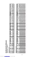
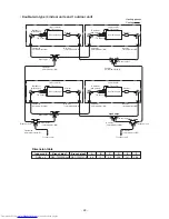
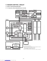
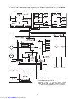
3. WIRING DIAGRAMS
"1:1 Model"
Connection
Interface
(Sold separately)
CN
33
4
(WHT)
1
CN41
TA
Indoor temp
sensor
TB01,0
2
TC,TCJ
Temp sensor
Terminal Block
F01,02
Symbol
DM
Drain Pump Motor
Fan Motor
Flo
at Switch
FM
FS
Fuse
Connector
Pa
rt
s Nam
e
CN
**
Wired Remote
Controller
(Sold separately)
Adapter for
Wireless Remote
Controller
(Sold separately)
A
B
TB02
B
A
BLK
BLK
BLK
WHT
2
1
3
CN
3
0
9
(BLU)
(YEL)
WHT
Power supply
220
V
60Hz
220-240V
50Hz
BLU : BLUE
BLK : BLACK
L
1
WHT : WHITE
YEL : YELLOW
RED : RED
COLOR
INDICATION
1
TB0
1
RED
3
BLK
N
Earth
Outdoor unit
Serial
sign
al
3
2
(WHT)
CN66
CN67
P01
5
(BLK)
In
do
or u
n
it
Earth screw
3
2
BL
K
1
T6.
3
A
250V
F01
1
(RED)
(WHT)
CN20
CN60
(WHT)
(YE
L
)
CN50
(WHT)
CN61
(W
HT)
(BLU)
2
1
U
3
MCC-1440
U4
2
CN51
CN40
1
(RED)
(BLU)
4
3
5
2
3
1
1
5
3
4
5
3
2
1
FAN DR
IVE
4
5
6
2
1
4
3
2
1
6
5
5
4
3
1
2
1
EXCT
1
22
Control P.C. Board
for Indoor Unit
MCC-1570
F02
T
3
.15A
-
+
+
250V
DC 7V
Power
supply
circuit
CN
3
2
DC20V
DC15V
DC12V
2
1
3
2
(W
HT)
CN
333
3
45
ON
CN70
(DISP)
CN72
CN7
3
(External static
(CHK)
CN71
2
1
(YEL)
CN104
CN101
(B
LK)
(RED)
CN102
SW
501
2
CN504
(WHT)
1
3
1
CN
3
4
(RED)
1
1
2
t°
2
t°
TC
TCJ
2
t°
1
TA
3
MS
FM
DM
FS
1
3
2
CN
8
0
(GRN)
CN50
8
(RED)
2
1
GRN : GREEN
sc
re
w
Power
supply
38
0V
3
N
60Hz
38
0-415V
3
N
50Hz
L2
1
L
3
Earth
Outdoor unit
Serial
si
gn
al
3
2
screw
N
P.C.Board
Co
nnector
Terminal
Terminal Block
Protectio
n
Ground
Field Wiring
Access
ory
pressure setup)
2
1
M
L1

