– 69 –
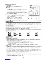
10-1-2. Forced Defrost Setup of Remote Controller (For wired remote controller only)
(Preparation in advance)
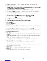
1
Push + + buttons simultaneously for 4 seconds or more on the remote controller.
(Push buttons while the air conditioner stops.)
The first displayed unit No. is the header indoor unit address in the group control.
2
Every pushing
UNIT LOUVER
button (button of the left side), the indoor unit No. in the group
control is displayed one after the other.
Select a main indoor unit (outdoor unit is connected) which is to be defrosted. In this time, fan and louver
of the selected indoor unit operate.
3
Using the set temperature
buttons, specify the CODE No. (DN)
8C
8C
8C
8C
8C
.
4
Using the timer time
buttons, set time to data
0001
0001
0001
0001
0001
. (
0000
0000
0000
0000
0000
at shipment)
5
Push button. (OK if indication lights)
6
Pushing button returns the status to the normal stop status.
(Practical operation)
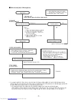
• Push ON/OFF
button.
• Select the HEAT mode.
• After a while, the forced defrost signal is sent to the outdoor unit and then the outdoor unit starts defrost operation.
(The forced defrost operation is performed for Max. 12 minutes.)
• After defrost operation finished, the operation returns to the heating operation.
To execute the defrost operation again, start procedure from above item
1
.
(If the forced defrost operation was executed once, setting of the above forced defrost operation is cleared.)
10-1-3. LED Display on P.C. Board
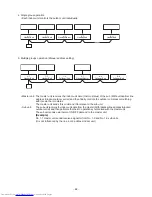
1. D501 (Red)
• It goes on (Goes on by operation of the main microcomputer) at the same time when the power supply is
turned on.
• It flashes with 1-second interval (every 0.5 second): When there is no EEPROM or writing-in operation
fails.
• It flashes with 10-seconds interval (every 5 second): During DISP mode
• It flashes with 2-seconds interval (every 1 second): While setting of function select (EEPROM)
2. D403 (Red)
• It goes on when power supply of the remote controller is turned on. (Lights on hardware)
3. D503 (Yellow): Main bus communication
• It goes on for 5 seconds in the first half of communication with the central controller.
4. D504 (Green): Sub bus communication
• It flashes for 5 seconds in the first half of communication with the remote controller. (Group header unit)
• It flashes with 0.2-second interval (for 0.1 second) for 5 second in the latter half of communication between
header and follower in the Gr indoor unit.
5. D14 (Orange)
• It flashes while receiving the serial signal from the outdoor unit. (Hardware)
6. D15 (Green)
• It flashes while sending the serial signal to the outdoor unit. (Hardware)


