


– 58 –
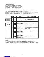
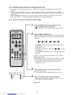
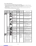
(3) Check procedures
Table 10-6-1
s
e
s
u
a
C
s
t
n
i
o
p
k
c
e
h
C
e
r
u
d
e
c
o
r
P
.
o
N
1
T
u
rn off the power
su
pply
b
re
a
ker
a
nd remove the P.C.
b
o
a
rd
ass
em
b
ly from electronic p
a
rt
s
bas
e. Remove the connecting
c
ab
le
s
from the termin
a
l
b
lock.
Check whether or not the f
us
e (F01)
i
s
b
lown.
Imp
u
l
s
e volt
a
ge w
as
a
pplied or the
indoor f
a
n motor
s
hort-circ
u
ited.
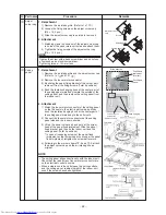
2
Remove the connector of the motor
a
nd t
u
rn on the power
su
pply
b
re
a
ker. If OPERATION indic
a
tor
fl
as
he
s
(once per
s
econd), it i
s
not
nece
ssa
ry to check
s
tep
s
(1 to
3
) in
the right next col
u
mn.
Check power
su
pply volt
a
ge :
1. Between No. 1
a
nd No.
3
of CN67
(AC 220–240V)
2. Between
a
nd
of
CN0
8
(DC
3
10–
3
40V)
3
. Between 12V
a
nd GND
4. Between 5V
a
nd GND
1. The termin
a
l
b
lock or the cro
ss
over
c
ab
le i
s
connected wrongly.
2. The c
a
p
a
citor (C01) V
a
ri
s
tor (R01),
line filter (L01), re
s
i
s
tor (R0
3
,R04), or
the diode (DB01) i
s
defective.
3
. T01 i
s
defective.
4. IC01,IC02
a
nd T01
a
re defective.
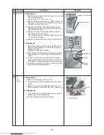
3
P
us
h [
]
bu
tton once to
s
t
a
rt the
u
nit. (Do not
s
et the mode to On-
Timer oper
a
tion.)
Check power
su
pply volt
a
ge :
1. Between No.1
a
nd No.
3
of CN67
(DC 15–60V)
IC0
8
a
nd IC0
9
a
re defective.
4
Shorten the re
s
t
a
rt del
a
y timer
a
nd
s
t
a
rt
u
nit.
Check whether or not
a
ll indic
a
tor
s
(OPERATION, TIMER, PRE. DEF, Hi
POWER)
a
re lit for
3
s
econd
s
a
nd
they ret
u
rn to norm
a
l
3
s
econd
s
l
a
ter.
The indic
a
tor
s
a
re defective or the
ho
us
ing
ass
em
b
ly (CN214) i
s
defective.
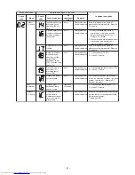
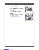
5
P
us
h [
]
bu
tton once to
s
t
a
rt the
u
nit.
• Shorten the re
s
t
a
rt del
a
y timer.
• Set the oper
a
tion mode to COOL.
• Set the f
a
n
s
peed level to AUTO.
• Set the pre
s
et temper
a
t
u
re m
u
ch
lower th
a
n the room temper
a
t
u
re.
(The
u
nit (compre
ss
or) oper
a
te
s
contin
u
o
us
ly in the
ab
ove
condition.)
1. Check whether or not the
compre
ss
or oper
a
te
s
.
2. Check whether or not the
OPERATION indic
a
tor fl
as
he
s
.
1. The temper
a
t
u
re of the indoor he
a
t
exch
a
nger i
s
extremely low.
2. The connection of the he
a
t exch
a
nger
s
en
s
or i
s
loo
s
e.
(The connector i
s
di
s
connected.)
(CN101,CN102)
3
. The he
a
t exch
a
nger
s
en
s
or
a
nd the
P.C.
b
o
a
rd
a
re defective.
(Refer to T
ab
le 10-4-1.)
4. The m
a
in P.C.
b
o
a
rd i
s
defective.
6
Connect the motor connector to the
motor
a
nd t
u
rn on the power
su
pply.
St
a
rt the
u
nit the following
condition.
• Set the f
a
n
s
peed level to HIGH.
(The
u
nit (compre
ss
or) oper
a
te
s
contin
u
o
us
ly in the
ab
ove
condition in No. 5.)
1. Check it i
s
impo
ss
i
b
le to detect the
volt
a
ge (DC15V)
b
etween No.4
a
nd No.5 of the motor termin
a
l
s
.
2. The motor doe
s
not oper
a
te or the
f
a
n motor doe
s
not rot
a
te with high
s
peed.
(B
u
t it i
s
po
ss
i
b
le to receive the
s
ign
a
l from the remote controller.)
3
. The motor rot
a
te
s
bu
t vi
b
r
a
te
s
s
trongly.
1. The indoor f
a
n motor i
s
defective.
(Protected oper
a
tion of P.C.
b
o
a
rd.)
2. The P.C.
b
o
a
rd i
s
defective.
3
. The connection of the motor
connector i
s
loo
s
e.


