– 47 –
Item
3. Outdoor fan
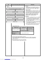
motor control
Operation flow and applicable data, etc.
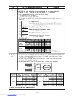
<Heating operation>
Description
Indoor unit A
Inverter
Outdoor unit
Compressor
Indoor unit B
Indoor unit C
Indoor unit D
Compressor revolution (rps)
Fan revolution
To > 10°C
Normal
5.5 < To < 10
operation
–5 < To < 5.5
To < –5
To > 10°C
SLEEP
5.5 < To < 10
operation
–5 < To < 5.5
To < –5
To is abnormal
—
~
20
~
34
34
~
Min.
Max.
Min.
Max.
Min.
Max.
300
390
510
600
550
670
390
390
600
600
670
670
450
450
670
670
670
670
450
450
670
670
670
670
300
390
390
510
390
510
390
390
510
510
510
510
390
390
510
510
510
510
390
390
510
510
510
510
300
390
390
510
550
670
1)
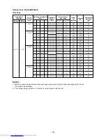
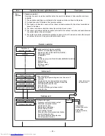
Four indoor units from A to D determine the respective instruction revolutions from the difference
between the remote controller setting temperature (Ts) and the indoor temperature (Ta), and
transmit this to the outdoor unit.
2) The outdoor unit receives the instructions from the indoor units, and the inverter operates the
compressor at the calculated revolutions.
3) The compressor operation range in each operating mode is shown in the table below:
4. Capacity
control
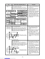
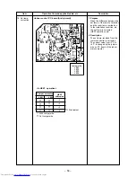
<Fan speed control>
Zone A: Decreased by 100 rpm every 20 seconds (to the MIN revolutions).
When Zone A operation continues for 5 minutes, the compressor is
stopped and then restarted.
Zone C: Decreased by 50 rpm every 20 seconds
(to the MIN revolutions).
Zone D: Maintained at the current revolutions.
Zone E: Increased by 50 rpm every 20 seconds
(to the MAX revolutions).
Zone B: Decreased by 100 rpm every 20 seconds
(to the MIN revolutions).
TE
24˚C
21˚C
18˚C
15˚C
Zone A :
Zone B :
Zone C :
Zone D :
Zone E :
∗
: In case that any multiple indoor units are combined.
To: Outdoor
sensor temp. (°C)
RAS-4M23SAV-E
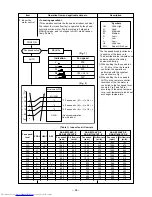
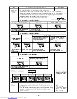
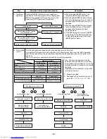
Basically, the fan speed is decided by the compressor speed and the outdoor temperature.
The fan speed is controlled between MIN. and MAX. as shown in the table below.
1) In the following cases, the outdoor fan is driven at MAX. speed.
• 3 minutes from start of compressor.
• 1 minute after defrosting operation ends.
2) The fan speed changes by the TE (outdoor heat exchanger sensor temperature) as shown in the
table below.
Operation
mode
COOL
No.of
operating
unit
1 unit
2 units
3 units
4 units
Combination
of indoor units
M10
M13
M16
¡
∗
¡
∗
¡
∗
Compressor
revolution
(rps)
16 to 38
16 to 60
16 to 72
24 to 68
32 to 74
37 to 80
Operation
mode
HEAT
No.of
operating
unit
1 unit
2 units
3 units
4 units
Combination
of indoor units
M10
M13
M16
¡
∗
¡
∗
¡
∗
Compressor
revolution
(rps)
16 to 72
16 to 77
16 to 90
24 to 100
32 to 100
37 to 100
Summary of Contents for RAS-4M23SACV-E
Page 27: ... 27 4 2 Outdoor Unit RAS 4M23SAV E RAS 4M23SACV E ...
Page 114: ... 114 MCC 1438 ...
Page 115: ... 115 MCC 818 ...


