


–
69
–
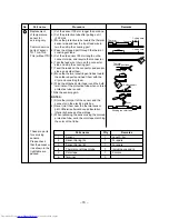
No.
Part name
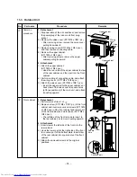
1
Electrolytic capacitor
(For raising pressure,
smoothing)
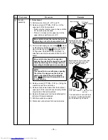
2
Converter module
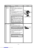
3
IGBT module
Checking procedure
1. Turn OFF the power supply breaker.
2. Discharge all four capacitors completely.
3. Check that safety valve at the bottom of capacitor is not broken.
4. Check that vessel is not swollen or exploded.
5. Check that electrolytic liquid does not blow off.
6. Check that the normal charging characteristics are shown in
continuity test by the tester.
C12, C13, C14, C15
→
500µF/400V
1. Turn OFF the power supply breaker.
2. Discharge all four capacitors completely.
3. Check that the normal rectification characteristics are shown in
continuity test by the tester.
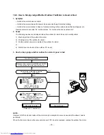
1.Turn OFF the power supply switch.
2. Discharge all four electrolytic capacitors completely.
3. Execute continuity test with a tester.
MCC-758
Soldered
surface
Heat sink IGBT side
C12
C13
C14
C15
Case that product is good
Pointer swings once, and
returns slowly. When
performing test once again
under another polarity, the
pointer should return.
1
0
-8-5. Checking Method for Each Part
+
~
–
~
A
2
1
+
~
1
–
~
2
A
Mark
E
G
E
G
Resistance value
in good product
Diode check
Tester rod
+
–
~
1
~
2
+
–
~
1
~
2
E
~
1
~
2
50kW or more
(0 in trouble)
Tester rod
U
V
W
U
V
W
W
V
U
W
V
U
1M or more 100k to 300k
200k to 300k
Case that product is good
IGBT check
Resistance value
in good product
50kW or more
(0 in trouble)
BZ BY BX
BW
BW
BZ
BV
BU
Tester rod
+
–
~
2
G
E
E
+
+
+
–
+
+
–
–
–
–
W
V
U
W
BV
BY
V
BU
BX
U
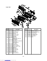
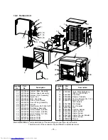
Summary of Contents for RAS-3M23YACV-E
Page 66: ... 66 10 8 2 P C Board Layout Top View Bottom View ...
Page 80: ... 80 CN600 MCC 758 ...
Page 81: ... 81 MCC 775 ...