background image

56

1

0

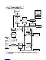
-5. Judgement of Trouble by Every Symptom

1

0

-5-1. Indoor unit (Including remote controller)

Turn off power

supply once, and 5

second later, turn it

on again.

Is OPERATION

lamp blinking?

NO

YES

NO

NO

YES

YES

Is it possible to

turn on power

supply by

pressing

[START/STOP]

button on

remote control?

Does

transmission

mark on

remote control
flash normally,

and is its signal

transmitted

properly?

Remote control is

defective.

Refer to (5)

“Troubleshooting for

Remote Control.”

Is fuse (F01)

of indoor control

board blown?

Is voltage

(DC 12V or 5V)

indicated on

rear of indoor

control board

normal?

Microcomputer

is defective.

Replace main

P.C. board.

Refer to

<Primary check>

or this problem

is one step short

of power P.C.

board block.

Is DC

310 – 340V

suppalied to

primary side of

transfer switch?

Are DC 15V,
DC 12V and

DC 7V

supplied to

secondary

side of

transfer
switch?

Turn off breaker

once and turn it

on again after

removing motor.

Transfer switch,

IC (IC01) for

power supply or

fan motor is

defective.

Replace motor.

YES

YES

NO

NO

NO

NO

YES

YES

YES

NO

NO

YES

Does

fan motor

connector

between 

1

and

2

short-circuit?

Unit operates

normally.

Are DC 15V,

DC 12V or

DC 7V

supplied to

secondary

side of

transfer
switch?

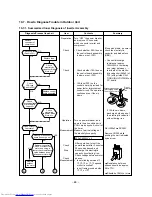
Operation

Measure

Item by symptoms

Check item

Conceivable principle 

cause

Parts

(R04, C01,

DB01, C03, R01

IC01 and T01)

are defective.

Be sure to disconnect the motor connector CN10 after shut off the power supply, or it will be a cause of
damage of the motor.

(1) Power is not turned on (Does not operate entirely)

Summary of Contents for RAS-3M23YACV-E

Page 1: ...SERVICE MANUAL FILE NO SVM 03016 AIR CONDITIONER SPLIT TYPE RAS M10UKCV E RAS M13UKCV E RAS M16UKCV E RAS 3M23YACV E R410A June 2003 ...

Page 2: ...4 WIRING DIAGRAM 17 5 SPECIFICATIONS OF ELECTRICAL PARTS 19 6 REFRIGERANT CYCLE DIAGRAM 20 7 CONTROL BLOCK DIAGRAM 22 8 OPERATION DESCRIPTION 24 9 INSTALLATION PROCEDURE 36 10 HOW TO DIAGNOSE THE TROUBLE 50 11 HOW TO REPLACE THE MAIN PARTS 71 12 EXPLODED VIEWS AND PARTS LIST 82 ...

Page 3: ...acity kW Cooling capacity range kW Power supply Electric characteristics Indoor Unit model Running current A Power consumption W Power factor Outdoor Unit model Running current A Power consumption W Power factor Starting current A COP Operating noise Indoor Unit model High dB A Medium dB A Low dB A Outdoor Unit model 10 1 unit operating dB A 3 units operating dB A Indoor unit Unit model Dimension ...

Page 4: ...1 99 to 8 01 4 5 1600 7 02 48 1 4 to 4 9 320 to 1750 1 90 to 7 68 5 4 1500 7 18 48 1 8 to 6 0 360 to 1880 2 34 to 9 00 5 4 1500 6 86 48 1 8 to 6 0 360 to 1880 2 24 to 8 60 5 4 1500 6 58 48 1 8 to 6 0 360 to 1880 2 14 to 8 25 5 8 1800 8 61 48 1 8 to 6 3 360 to 1970 2 34 to 9 43 5 8 1800 8 24 48 1 8 to 6 3 360 to 1970 2 24 to 9 02 5 8 1800 7 89 48 1 8 to 6 3 360 to 1970 2 14 to 8 64 5 9 1830 8 76 48...

Page 5: ...ipe length 5m 3 3 units operating 220V 240V 230V 105 115 110 100 105 100 95 90 85 0 95 90 85 80 75 70 65 60 55 50 32 34 36 38 40 42 44 46 14 16 43 18 20 22 24 Outdoor temp C Capacity ratio 100 6 7 kW Indoor air wet bulb temp C Capacity ratio Capacity ratio Conditions Indoor DB27 C Outdoor DB35 C Indoor air flow High Pipe length 5m 3 3 units operating Conditions Indoor DB27 C WB19 C Indoor air flow...

Page 6: ... 06 12 06 20 95 12 06 12 06 20 95 12 06 12 06 20 95 4 55 4 55 7 67 7 10 7 10 12 26 8 61 8 61 14 98 8 03 8 03 13 81 9 66 9 66 16 75 50 240 1 198 264 9 84 9 84 17 07 9 84 9 84 17 07 9 94 9 94 17 25 10 05 10 05 17 45 10 08 10 08 17 38 11 55 11 55 20 03 11 55 11 55 20 03 11 55 11 55 20 03 Compressor Fan motor FLA MSC RLA Indoor Outdoor 3 47 3 47 0 15 x 1 0 15 0 5 5 69 5 69 0 15 x 1 0 15 0 5 7 01 7 01 ...

Page 7: ...re as shown in Table 2 2 1 Never use copper pipes thinner than 0 8 mm even when it is available on the market This air conditioner adopts the new refrigerant HFC R410A which does not damage the ozone layer The working pressure of the new refrigerant R410A is 1 6 times higher than conventional refrigerant R22 The refrigerating oil is also changed in accordance with change of refrigerant so be caref...

Page 8: ...2 2 Processing of Piping Materials When performing the refrigerant piping installation care should be taken to ensure that water or dust does not enter the pipe interior that no other oil other than lubricating oils used in the installed air conditioner is used and that refrigerant does not leak When using lubricating oils in the piping processing use such lubricating oils whose water content has ...

Page 9: ...s related to flare processing for R22 Nominal Outer Thickness diameter diameter mm mm 1 4 6 35 0 8 3 8 9 52 0 8 1 2 12 70 0 8 5 8 15 88 1 0 A mm Flare tool for Conventional flare tool R22 clutch type Clutch type Wing nut type 0 to 0 5 0 5 to 1 0 1 0 to 1 5 0 to 0 5 0 5 to 1 0 1 0 to 1 5 0 to 0 5 0 5 to 1 0 1 5 to 2 0 0 to 0 5 0 5 to 1 0 1 5 to 2 0 Table 2 2 5 Flare and flare nut dimensions for R41...

Page 10: ...entional R22 Incidentally when the torque is weak the gas leakage may occur When it is strong the flare nut may crack and may be made non removable When choos ing the tightening torque comply with values designated by manufacturers Table 2 2 7 shows reference values Note When applying oil to the flare surface be sure to use oil designated by the manufacturer If any other oil is used the lubricatin...

Page 11: ... to the above exclusive tools the following equipments which serve also for R22 are necessary as the general tools 1 Vacuum pump Use vacuum pump by attaching vacuum pump adapter 2 Torque wrench For Ø6 35 3 Pipe cutter 4 Reamer 5 Pipe bender 6 Level vial 7 Screwdriver 8 Spanner or Monkey wrench 9 Hole core drill Ø65 10 Hexagon wrench Opposite side 5mm 11 Tape measure 12 Metal saw Also prepare the f...

Page 12: ... the status as it is for 1 to 2 minutes and ensure that the compound gauge s pointer does not return Set the refrigerant cylinder to the electronic balance connect the connecting hose to the cylinder and the connecting port of the electronic balance and charge liquid refrigerant Never charge refrigerant exceeding the specified amount If the specified amount of refrigerant cannot be charged charge ...

Page 13: ...Phosphor bronze brazing filler Phosphor bronze brazing filler is generally used to join copper or copper alloy 3 Low temperature brazing filler Low temperature brazing filler is generally called solder and is an alloy of tin and lead Since it is weak in adhesive strength do not use it for refrigerant pipes Phosphor bronze brazing filler tends to react with sulfur and produce a fragile compound wat...

Page 14: ...n the Nitrogen gas is flowing be sure to keep the piping end open Adjust the flow rate of Nitrogen gas so that it is lower than 0 05 m3 Hr or 0 02 MPa 0 2kgf cm2 by means of the reducing valve After performing the steps above keep the Nitrogen gas flowing until the pipe cools down to a certain extent temperature at which pipes are touchable with hands Remove the flux completely after brazing Fig 2...

Page 15: ...26 45 190 40 32 64 590 320 620 235 235 215 215 90 90 275 45 150 150 160 160 120 80 53 6 60 Hanger Hanger Hanger Hanger Hanger Drain hose 0 54m Connecting pipe 0 43m Flare 6 35 For stud bolt 8 10 For stud bolt 6 Installation plate outline Center line Minimum distance to ceiling 170 or more Minimum distance to ceiling 170 or more 65 or more Minimum distance to ceiling Wireless remote control 57 18 1...

Page 16: ...ide line of product Outside line of product 600 310 B C A D 4 ø11 17U shape hole For ø8 ø10 anchor bolt Mounting dimensions of anchor bolt 50 or more Intake Intake 100 or more 250 or more 200 or more Minimum distance from wall Outside line of product Outlet 4 ø11 17 long hole For ø8 ø10 anchor bolt 8 687 695 Hanger 123 8 332 86 2 53 53 53 53 53 Z Charging port Valve cover For installation of the o...

Page 17: ...fuse blows out Check the R04 of the varistor Check the voltage at the No 4 pin on CN13 connector of the infrared receiver Check the transformer and the power supply circuit of the rated voltage Check for voltage at the while lead of louver motor Check the transformer and the power supply circuit of the rated voltage Check the voltage at the No 1 pin on CN10 connector Check the DB01 R05 and C03 Ref...

Page 18: ...T WHI YEL ORN BLU RED GRY ORN PNK WHI CN501 P12 P13 P11 P14 YEL YEL PUR CN704 BLK BLK PNK YEL RED WHI BLK GRY P04 RED P05 WHI BRW RED ORN YEL BLK BRW RED ORN YEL P06 CN15 P02 GRY ORN BLK BLK BLK BLK BLK P01 L 3 2 1 3 2 1 1 2 3 1 2 3 4 4 5 5 2 2 1 1 N 1 2 3 1 2 3 P03 1 1 2 2 CN02 CN03 CN05 CN14 CN13 1 1 2 2 3 3 1 1 2 2 1 1 2 2 3 3 6 6 5 5 4 4 3 3 2 2 1 1 6 6 5 5 4 4 3 3 2 2 1 1 P M V PULSE MODULATI...

Page 19: ... 7 5V x 1 13V x 1 26 5V x 3 16V x 1 15V x 1 3 Reactor CH38Z K L 10mH 16A x 2 4 Outside fan motor ICF 140 40 8 DC140V 40W 5 Fan control relay AJQ1341 Coil DC12V Contact AC125V 3A 6 Discharge temp sensor Inverter attached 62kΩ 20 C TD sensor 7 Outside air temp sensor Inverter attached 10kΩ 25 C TO sensor 8 Temp sensor at A room Inverter attached 10kΩ 25 C gas side TGa sensor 9 Temp sensor at B room ...

Page 20: ... Temp measurement To C room To B room Indoor heat exchanger Cross flow fan Sectional shape of heat insulator To C room To B room Allowable height difference 10m Allowable pipe length Per 1 unit Max 20m Min 2m Total Max 40m P Strainer Pulse modulating valve at liquid side SEV15RC2 TGa TGb TGc TD Accumulating tank Ø51 x 300 460cc Compressor DA130A1F 21F T2 Outdoor heat exchanger Temp measurement Pro...

Page 21: ...ns of indoor units 10 13 16 10 10 13 10 16 10 13 13 16 13 16 16 10 10 10 13 10 10 16 10 10 13 13 10 Standard Surface temp of pressure heat exchanger P Mpa T1 C T2 C 0 92 11 42 0 85 9 47 0 73 8 50 0 96 10 5 to 11 5 49 0 92 11 to 12 51 0 92 11 to 12 51 0 92 11 to 12 51 0 92 11 to 12 51 0 92 11 to 12 51 1 04 12 5 to 13 5 51 0 98 12 to 13 52 0 98 12 to 13 52 0 98 12 to 13 52 Fan speed Compressor revol...

Page 22: ...Infrared Rays Signal Receiver Initiallizing Circuit Clock Frequency Oscillator Circuit Power Supply Circuit Noise Filter From Outdoor Unit M C U Functions Louver Control 3 minute Delay at Restart for Compressor Motor Revolution Control Processing Temperature Processing Timer Louver ON OFF Signal Louver Driver Relay RY04 Outdoor Unit Operation Display Timer Display Filter Sign Display Indoor Fan Mo...

Page 23: ... Signal communication to MCU M C U Input current Sensor Over current sensor Over current sensor Converter AC DC Inverter DC AC Inverter DC AC Noise filter High power factor correction circuit Over current detect circuit Over current detect circuit Rotor position detect circuit Rotor position detect circuit Gate drive circuit Gate drive circuit Inverter output frequency control A D converter functi...

Page 24: ... setting of the indoor heat ex changer by using heat exchanger sensor Prevent freezing control Louver motor control Indoor fan motor operation control LED display control Transferring of operation command signal Serial signal to the outdoor unit Reception of information of operation status Serial signal including outside temp data to the outdoor unit and judgment display of error 2 Role of outdoor...

Page 25: ...ting unit indoor units revolution rps RAS M16UKCV E 16 to 77 1 unit RAS M13YKCV E 16 to 72 RAS M10YKCV E 16 to 45 2 units 19 to 84 3 units 23 to 92 In case that any multiple indoor units are combined 8 1 2 Current Release Control The outdoor main circuit control section Inverter assembly detects the input current to the outdoor unit If the current value with compressor motor speed instructed from ...

Page 26: ...by non step variable system of the revolution speed the revolution speed is restricted to three steps on the convenience of controlling If a strong wind is lashing outside of the room the operation may be continued as the outdoor fan stops in order to protect the outdoor fan motor If a fan lock occurred due to entering of foreign matter the air conditioner stops and an alarm is displayed Table 8 1...

Page 27: ...position the indoor fan motor operates as shown in Fig 8 2 1 When the FAN SPEED button is set to LOW MED or HIGH the motor operates with a constant air flow ECONO mode cannot be set 8 2 2 Cooling Operation The Remote Control MODE Button is Set to the COOL Position Once the setting is made the operation mode is memorized in the microcomputer so that the same operation can be effected thereafter sim...

Page 28: ... 2 1 Current value Current limit 11 9 5 12 9 0 4 Outdoor temperature release control The outdoor temperature release is controlled by changing the current release points 11 and 12 in the above item according to temperature de tected by the outdoor temperature sensor For example if the outdoor temperature is over 40 C the value of current release point be comes 7 7A 5 Limit for maximum compressor m...

Page 29: ... operating motor speed 1 Indoor air flow is controlled between SUL and L Low air 2 Setting M10UKCV E at 16 rps M13UKCV E at 20 rps and M16UKCV E at 26 rps as the maximum operating compressor motor speed the minimum capacity operation range is widened every 1 hour and 2 hours have passed after ECONO operation had started 3 Maximum operating compressor motor speed lowers up to 37 rps when the ECONO ...

Page 30: ...so any change in room temperature The compressor operates with maximum 28 rps for 1 minute when started and restarted When the air conditioner operates in Dry mode the maximum compressor motor speed is restricted M10UKCV E Max 22 rps M13UKCV E Max 28 rps M16UKCV E Max 32 rps While multiple indoor units operate compres sor motor speed is calculated in the outdoor unit to operate When room temperatu...

Page 31: ...s accepted Using the Auto Restart function the Temporary Auto operation starts when power failure is reset 8 3 2 Temporary Cooling Operation When the TEMPORARY operation button keeps pushed for 10 seconds Cooling operation of which compressor motor speed and the indoor fan speed are fixed starts Compressor motor speed 28 rps Indoor fan speed Low When the TEMPORARY operation button is pushed again ...

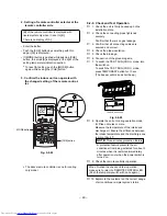
Page 32: ...t automatically The above Auto Restart settings can be carried out When the system is stand by not operating When the system is operating Operation Push the TEMPORARY button continuously more than three seconds Motion Stand by The system starts to operate The green light goes on about three seconds after The unit beeps three times The orange light goes on The system is operating If the system is n...

Page 33: ... more than three seconds Motion Operating The orange light goes on The system stops to operate The orange light goes off about three seconds after The unit beeps three times The system stops If the system is not required to stop at this time use the remote control and to restart During subsequent operation the green light goes on 2 If OFF TIMER operation is reserved without setting of Auto Restart...

Page 34: ...9 9 9 On timer button ON Press this button to set the ON timer Reserve button SET Press this button to reserve time settings A receiving beep is heard Cancel button CLR Press this button to cancel ON timer and OFF timer A receiving beep is heard High power button Hi POWER Press this button to start the high power operation Memory button MEMO Press this button to stand by memorizing the settings Pr...

Page 35: ...ls LOW LOW MED MED HIGH can be indicated Indicates AUTO when the operating mode is either AUTO or Dry 6 6 6 6 6 TIMER and clock time display The time set for timer operation or clock time is indicated The present time is always indicated except for TIMER operation 7 7 7 7 7 Hi POWER display Indicates when the Hi POWER operation starts Press the Hi POWER button to start and press it again to stop t...

Page 36: ... PLACE THE UNIT WELL AWAY MORE THAN 2 M FROM HEAT SOURCES SUCH AS RADIATORS HEAT REGISTORS FURNACE STOVES ETC WHEN MOVING THE AIR CONDITIONER FOR INSTALLING IT IN ANOTHER PLACE AGAIN BE VERY CAREFUL NOT TO GET THE SPECIFIED REFRIGERANT WITH ANY OTHER GASEOUS BODY INTO THE REFRIGERATION CYCLE IF AIR OR ANY OTHER GAS IS MIXED IN THE REFRIGERANT THE GAS PRESSURE IN THE REFRIGERATION CYCLE BECOMES ABN...

Page 37: ... port size have been changed to 1 2 UNF 20 threads per inch When purchasing a charge hose be sure to confirm the port size As pressure is high and gasification speed is fast it is difficult to read the indicated value by means of charging cylinder as air bubbles occur The size of opposite sides of flare nuts have been increased Incidentally a common wrench is used for nominal diameters 1 4 and 3 8...

Page 38: ...ar right Bottom right Bottom left Do not allow the drain hose to get slack Cut the piping hole sloped slightly Make sure to run the drain hose sloped downward 8 Flat head wood screw RAS M13UKCV E 9 2 Indoor unit RAS M16UKCV E Insulate the refrigerant pipes separately with insulation not together 6 mm thick heat resisting polyethylene foam Part name Q ty Mounting screw 4 x 25 s x 6 Flat head wood s...

Page 39: ...nterference The location of the remote control should be determined as shown below CAUTION Direct sunlight to the indoor unit wireless receiver should be avoided The microprocessor in the indoor unit should not be too close to r f noise sources For details see the owner s manual Top view Indoor unit Axial distance Reception range Reception range Remote control Indoor unit Remote control Side view ...

Page 40: ... inlet grille Open the air inlet grille upward and pull it toward you 2 Remove the terminal cover and cord clamp 3 Insert the connecting cable according to the local cords into the pipe hole on the wall 4 Take out the connecting cable through the cable slot on the rear panel so that it protrudes about 15 cm from the front 5 Insert the connecting cable fully into the terminal block and secure it ti...

Page 41: ...ne trouble make sure to insulate both the connecting pipes Use polyethylene foam as insulating material When bending a pipe carefully do it not to crush it NOTE If the pipe is bent incorrectly the indoor unit may unstably be set on the wall After passing the connecting pipe through the pipe hole connect the connecting pipe to the auxiliary pipes and wrap the facing tape around them Installation pl...

Page 42: ...nit and remote controller are different There is no relation between A setting B setting and A room B room when connecting the piping and cables 1 Setting of remote controller switch at the indoor unit side Fig 9 2 19 How to remove the front cabinet 1 Stop the operation of the air conditioner and turn turn off its main power supply 2 Pull the air inlet grille toward you to open it and remove the a...

Page 43: ...tch the TEST RUN COOL mode turn the switch on To switch the TEST RUN COOL mode press TEMPORARY button for 10 sec The beeper will make a short beep The above remote controller is one for cooling only model CHK button Fig 9 2 23 8 Operate the unit at cooling operation mode for fifteen minutes or more Measure the temperature of the intake and discharge air Ensure the difference between the intake tem...

Page 44: ... not raise any problem 9 3 4 Optional Installation Parts Local Supply CAUTION 1 Install the outdoor unit without anything blocking the air discharging 2 When the outdoor unit is installed in a place exposed always to a strong wind like a coast or on a high story of a building secure the normal fan operation using a duct or a wind shield 3 Specially in windy area install the unit to prevent the adm...

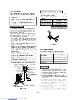
Page 45: ...uter dia of copper pipe 6 35 9 52 12 7 R410A R22 1 5 to 2 0 1 0 to 1 5 1 5 to 2 0 1 0 to 1 5 2 0 to 2 5 1 5 to 2 0 Flaring size A Unit mm Outer dia of copper pipe 6 35 9 52 12 7 A R410A R22 9 1 9 0 13 2 13 0 16 6 16 2 0 0 4 In the case of flaring for R410A with the conven tional flare tool pull out it approx 0 5 mm more than that for R22 to adjust to the specified flare size The copper pipe gauge ...

Page 46: ...oor unit will not fall 5 When the outdoor unit is to be mounted high on a wall take particular care to ensure that parts do not fall installer is protected 6 When doing installation work on level ground it is usual to wiring and piping connections to the indoor units And then make to the outdoor unit However if outdoor work is difficult it is possible instead to make changes to the procedure For e...

Page 47: ...9 3 12 Packed valve handling precautions Open the valve stem all the way out do not try to open it beyond the stopper Securely tighten the valve stem cap in torque is as follows Gas side Ø12 7 mm Gas side Ø9 52 mm Liquid side Ø6 35 mm Service port 50 to 62 N m 5 0 to 6 2 kgf m 33 to 42 N m 3 3 to 4 2 kgf m 14 to 18 N m 1 4 to 1 8 kgf m 14 to 18 N m 1 4 to 1 8 kgf m Hexagonal wrench is required Fig...

Page 48: ...nnected to the mains Connection to fixed wiring A switch or circuit breaker which disconnects all poles and has a contact separation of at least 3 mm must be incorporate in the fixed wiring An approved short circuit breaker or switches must be used A breaker having a sensitivity of approxi mately 0 1 second or less and a capacity of approximately 30 mA is usually used Three room A B C Multi Fig 9 ...

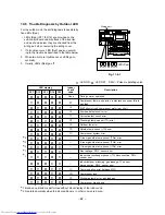
Page 49: ...using five LEDs Red Refer to the table in page 68 for more details LEDs Red D11 to D15 locate on the sub control borad underneath of the inverter 1 If a trouble occurs LED Red goes on according to the contents of trouble as shown in the table in page 68 2 When two or more troubles occur LEDs go on 3 Usually LEDs Red go off Self Diagnosis by LED Indication cyclically alternately Wiring port D11 D12...

Page 50: ...1 51 52 53 56 62 63 64 70 NOTE A large capacity electrolytic capacitor is used in the outdoor unit controller inverter Therefore if the power supply is turned off charge charging voltage DC280V remains and discharging takes a lot of time After turning off the power source if touching the charging section before discharging an electrical shock may be caused Discharge the electrolytic capacitor comp...

Page 51: ...does not change even though FAN air flow select button is operated Increasing of compressor motor speed stops approx 30 seconds after operation started and then compressor motor speed increases again approx 30 seconds after The set value of the remote control should be below the room temperature Description The OPERATION lamp of the indoor unit flashes when power source is turned on If START STOP ...

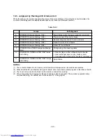
Page 52: ...ATION lamp is blinking 5Hz C OPERATION lamp is blinking 5Hz D OPERATION lamp is blinking 5Hz E OPERATION lamp is blinking 5Hz F OPERATION and TIMER lamps are blinking 5Hz G OPERATION TIMER and FAN ONLY lamps are blinking H OPERATION TIMER and FAN ONLY lamps are blinking Power failure when the power supply is turning on Thermo sensor TA short or break Heat exchanger sensor TC short or break Indoor ...

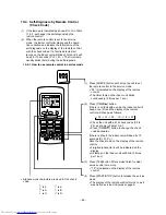
Page 53: ... remote control The timer lamp on the indoor unit blinks continuously 5 times per 1 sec 4 Press START STOP button to release the service mode The display of the remote control returns to as it was before service mode was engaged 2 Press TIMER 8 button If there is no fault with a code the indoor unit will beep once Pi and the display of the remote control will change as follows 00 01 02 1d 1E 22 Ch...

Page 54: ...ing operation check compressor thermo operation and supply gas check gas leak also 3 Unit operates normally during check If Return serial signal does not stop between indoor terminal board 2 and 3 replace inverter P C board If signal stops between indoor terminal board 2 and 3 replace indoor P C board If Operation command signal does not stop between indoor terminal board 2 and 3 replace inverter ...

Page 55: ...yed when error is detected Displayed when error is detected Displayed when error is detected Displayed when error is detected Displayed when error is detected Judgment and action Even if trying operation again all operations stop immediately Replace P C board 1 Even if connecting lead wire of compressor is removed position detect circuit error occurred Replace P C board 2 Measure resistance betwee...

Page 56: ...ry check or this problem is one step short of power P C board block Is DC 310 340V suppalied to primary side of transfer switch Are DC 15V DC 12V and DC 7V supplied to secondary side of transfer switch Turn off breaker once and turn it on again after removing motor Transfer switch IC IC01 for power supply or fan motor is defective Replace motor YES YES NO NO NO NO YES YES YES NO NO YES Does fan mo...

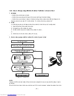
Page 57: ...h Indoor P C board is replaced Confirmation procedure YES YES NO NO To item of Power is not turned on Turn on power supply Does operation lamp flash Is wired correctly to white and black lead wires of terminal board Correct wiring 57 ...

Page 58: ... Then press START STOP button on remote control to stop blinking lamp on indoor unit Replace indoor fan motor Replace main P C board Is it possible to detect DC 15V between 4e and 3d of motor connector CN10 Turn off indoor unit and remove connector from motor Then start to operate indoor unit with remote control Start to operate the indoor unit At this time is it possible to detect DC 1V or more b...

Page 59: ...0 connector while the fan rotating NOTE Do not disconnect the connector while the fan rotates Use a thin tester rod Indoor fan starts rotating when power supply breaker is turned ON Check output voltage DC of the fan motor on P C board Measure the voltage of the motor connector CN10 pin 2 GND Black and pin 3 V line Yellow under condition that the indoor fan rotates Above DC 0 4V P C board is defec...

Page 60: ... tone be heard in a transistor radio when transmitting within 5cm distance from the radio Does the transmission indicator light Is there any receiving sound and operation Short circuit ACL switch with a coin or others at rear side of remote controller Replace P C board Replace the battery Normal Remote controller is failure NO YES NO YES NO YES NO YES NO YES NO YES NO YES Is Temporary Cool operati...

Page 61: ...urement should be performed 2 minutes and 30 seconds after starting of the operation Be sure to prepare a diode for judgment Fig 11 5 1 Normal time Voltage swings between DC15 and 60V Abnormal time Voltage does not vary 2 Outdoor unit stops in a little while after operation started Check procedure Select phenomena described below 1 The outdoor unit stops 10 to 20 minutes after operation started an...

Page 62: ... l Indoor check code None 07 14 16 17 19 1A 1B 1C 1C 1D 1E 1F Description During normal operation Compressor thermo operation instantaneous power failure gas leak IGBT short circuit compressor motor rear short Position detect circuit error Current detect circuit error Discharge temp sensor TD error Outdoor fan error Outside temp sensor TO error Compressor system error A room gas side temp sensor T...

Page 63: ...the electrolytic capacitor and diode block DB01 Connect discharge resistance approx 100Ω40W or soldering iron plug between terminals of the electro lytic capacitor 500µF of C15 with printed CAU TION HIGH VOLTAGE on P C board If 15A fuse is blown discharge both edges of the electrolytic capacitor with soldering iron OK if 500µF DC280V Remove CN300 while pushing the part indicated by an arrow Resist...

Page 64: ...g of compressor Check fan motor position detect signal Replace com pressor C B A Replace outdoor fan motor Replace control board assembly Replace control board Replace compressor Check compressor winding resistance 10 8 How to Check Simply the Main Parts 10 8 1 How to Check the P C Board Indoor Unit 1 Operating precautions 1 When removing the front panel or the P C board be sure to shut off the po...

Page 65: ...age check 1 Voltage of relay coil DC 12V Between pin 10 of IC31 and GND Between pin 11 of IC31 and GND 2 Between No 1 and 2 of connecting cable terminal block 220 230 240V AC 1 All indicators light for 3 sec 2 Indicators do not indicate normally after approximate 3 sec 1 Compressor does not operate 2 OPERATION lamp flashes 1 The voltage of DC 35V is not measured between the red and black of the mo...

Page 66: ... 66 10 8 2 P C Board Layout Top View Bottom View ...

Page 67: ...e k Temperature C TD Discharge temp sensor TA Room temp sensor TC Heat exchanger temp sensor TO Outdoor temp sensor TGa Gas side temp sensor TGb Gas side temp sensor TGc Gas side temp sensor TGd Gas side temp sensor TA TC TO TGa TGb TGc TGd TD Sensor characteristic table ...

Page 68: ...otor Model ICF 140 40 8 3 Compressor thermo Bimetal type Model PW 2AL 4 Outdoor temperature sensor TO pipe temperature sensor TGa TGb TGc discharge temperature sensor TD Checking procedure Measure the resistance value of each winding by using the tester Measure the resistance value of winding by using the tester For details refer to Section 11 9 Check conduction by using the tester Disconnect the ...

Page 69: ...fication characteristics are shown in continuity test by the tester 1 Turn OFF the power supply switch 2 Discharge all four electrolytic capacitors completely 3 Execute continuity test with a tester MCC 758 Soldered surface Heat sink IGBT side C12 C13 C14 C15 Case that product is good Pointer swings once and returns slowly When performing test once again under another polarity the pointer should r...

Page 70: ...tor does not rotate Outdoor fan motor stops within several tens seconds though it started rotating Outdoor fan motor rotates or does not rotate according to the position where the fan stopped etc Remote control check code 02 Outdoor block 1A Outdoor fan drive system error 2 Cause The following causes are considered when the outdoor fan motor does not normally rotate 1 Mechanical lock of the outdoo...

Page 71: ...nection remove the 2 screws for the electrical part box and remove the screw from the LED unit Then remove the LED unit and the electrical part box from the main unit How to mount the electrical part 1 To put back the electrical part box lock it to the upper hook of the back body 2 Tighten the 2 screws on the electrical part box 3 Connect the 3 connectors and arrange the wiring same as original co...

Page 72: ...cross flow fan then separate the fan and the fan motor Notice To assemble cross flow fan and fan motor to the unit please turn the fan motor unit the center of its terminal meets the lowest point of band motor R point A Fix the cross flow fan with the set screw at the position where the gap between the back body and the right surface of the cross flow fan is 4 mm 1 Remove the front panel electrica...

Page 73: ...ion of air conditioner 2 Remove the front panel Remove the two fixing screws φ4 x 14l 3 Remove the electrical part base No Q Remarks Replace the thermal fuse terminal block microcomputer ass y and the P C board ass y Part name Common procedure 11 2 Microcomputer ...

Page 74: ... pcs Insert the upper part to the upper cabinet set hook claw of the valve cover to square holes at three positions of the main unit and attach it pushing upward 1 Detachment 1 Perform work of item 1 of 2 Remove screw ST1TØ4 x 10l l l l l 1 pc of the front cabinet and inverter cover and screws ST1TØ4 x 10l l l l l 3 pcs of the front cabinet and lower part of the front cabinet and motor base ST1TØ4...

Page 75: ...it is incorporated in it 3 Perform discharging by connecting polarity by discharging resistance approx 100Ω40W or plug of soldering iron to terminals of the C15 printed CAUTION HIGH VOLTAGE is attached electrolytic capacitor 500µF on P C board Be careful to discharge the capacitor because the electrolytic capacitor cannot naturally discharge and voltage remains according to trouble type in some ca...

Page 76: ...se modulating valve 6P Green CN13 B room pulse modulating valve 6P Red CN14 A room pulse modulating valve 6P Black 2 Disconnect cable connecting the main control board assembly side and sub control board assembly Main control board assembly side CN704 Connecting cable 4P White Sub control board assembly side CN15 Connecting cable 4P White 3 Remove the control board assembly from P C board base 1 M...

Page 77: ...move the sound insulation material 5 Remove terminal cover of the compressor and disconnect lead wire of the compressor thermo and the compressor from the terminal 6 Remove pipe connected to the compressor with a burner 7 Remove the fixing screw of the bottom plate and heat exchanger ST1TØ4 x 10l l l l l 1 pc 8 Remove the fixing screw of the bottom plate and valve clamping plate ST1TØ4 x 10l l l l...

Page 78: ...ve is connected to CN13 Check that coil at C room side Green marking is marked on the pulse modulat ing valve is connected to CN12 of the control board assembly respectively 1 Detachment 1 Perform work of item 1 of and 2 Remove the front cabinet and put it down so that fan guard side directs downward Perform work on a corrugated cardboard cloth etc to prevent flaw to the product 3 Remove the hooki...

Page 79: ...or sides and solder them 8 Move the thermal constringent tubes toward the soldered parts and heat them with the dryer and constring them 9 Wind the attached color tape round the both terminals of the protective tube when colored protective tube is used 10 Fix the sensor again NOTES 1 Store the joint part of the sensor and the connector in the electric parts box 2 Never joint them near the thermal ...

Page 80: ... 80 CN600 MCC 758 ...

Page 81: ... 81 MCC 775 ...

Page 82: ...ock 3P AC 300V 20A 403 43T69320 Temperature Sensor 404 43T69003 Cord Clamp 405 43T69079 P C Board Ass y WRS LED Location Part No Description No 406 43T69333 P C Board Ass y MCC 867 RAS M10UKCV E 406 43T69334 P C Board Ass y MCC 867 RAS M13UKCV E 406 43T69335 P C Board Ass y MCC 867 RAS M16UKCV E 406 401 404 402 403 405 TC 10kΩ 25 C TC 10kΩ 25 C ...

Page 83: ...3T49006 Holder Plate EVA Seal 218 43T79302 Guide Drain Bearing 220 43T39301 Base Bearing 221 43T20302 Fan Cross Flow 222 43T39302 Band Motor L 223 43T21327 Motor Fan Location Part No Description No 226 43T69310 Remote Controller 227 43T83003 Holder Remote Controller 229 43T62302 Terminal Cover 231 43T60317 Cord Motor Louver 232 43T60316 Cord Motor Fan 233 43T07303 Holder Pipe 234 43T01303 Mark 208...

Page 84: ...tion No No Location Part Description No No 17 43046351 Valve Pulse Modulating P M V SEV15RC2 18 43046347 Coil P M V 19 43058264 Reactor CH38Z K 20 43050298 Thermo Bimetal CS 7 125 21 4302C019 Motor Fan DC ICF 140 40 4 22 43047549 Nut Flange 23 43020312 Fan Propeller 24 43097166 Nut 25 43049643 Cushion Rubber 26 43063187 Holder Sensor 27 43049654 Holder Sensor 28 43063195 Holder Thermo Bimetal 29 4...

Page 85: ...pe 707 4306A030 Terminal block 9P Location Part Description No No Location Part Description No No 708 43062231 Base P C Board 709 43063308 Heatsink 710 4306S191 P C Board Assembly MCC 758 711 4306S190 P C Board Assembly MCC 775 12 3 P C Board Layout 4 4 3 2 1 4 3 2 1 709 710 708 705 707 711 703 TO Sensor TGb Sensor TGa Sensor TGc Sensor TD Sensor 702 704 706 ...

Page 86: ...TOSHIBA CARRIER THAILAND CO LTD 144 9 MOO 5 BANGKADI INDUSTRIAL PARK TIVANON ROAD TAMBOL BANGKADI AMPHUR MUANG PATHUMTHANI 12000 THAILAND ...

Reviews: