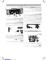
background image

3

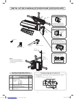
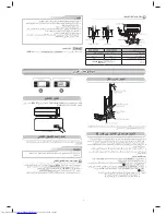
To unit out line 

240mm

To unit out line 

35mm

To unit out line 

240mm

Of
fset 23mm from the right side edge is

the center of pipe hole

To unit out line 

120mm

0

23

35

120

180

240

Of

fset 85mm from the left side edge is

the center of pipe hole

170

170

5

0

4

0

85

132

23

65


mm

m from the r

ight side edge is

e

 center of pipe hole

35

120

180

240

23 mm

65 

mm

5

4

45

5

7

INDOOR UNIT

INDOOR UNIT

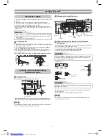
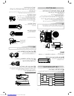
Installation Place

Remote control

  A place where there are no obstacles such as a curtain that may block the 

signal from the remote control.

  Do not install the remote control in a place exposed to direct sunlight or 

close to a heating source such as a stove.

  Keep the remote control at least 1 m apart from the nearest TV set or 

stereo equipment. (This is necessary to prevent image disturbances or 
noise interference.)

  The location of the remote control should be determined as shown below.

Cutting a Hole and Mounting

Installation Plate

When the installation plate is directly mounted

on the wall

1. Securely fi t the installation plate onto the wall by screwing it in the upper 

and lower parts to hook up the indoor unit.

2. To mount the installation plate on a concrete wall with anchor bolts, use 

the anchor bolt holes as illustrated in the below fi gure.

3. Install the installation plate horizontally in the wall.

NOTE

  When drilling a wall that contains a metal lath, wire lath or metal plate, be 

sure to use a pipe hole brim ring sold separately.

  A place which provides the spaces around the indoor unit as shown in the 

diagram

  A place where there are no obstacles near the air inlet and outlet

  A place which allows easy installation of the piping to the outdoor unit

  A place which allows the front panel to be opened

  The indoor unit shall be installed as top of the indoor unit comes to at 

least 2 m height. Also, it must be avoided to put anything on the top of the 
indoor unit.  

The center of the pipe hole is 
above the arrow.

Pipe hole

  In case of block, brick, concrete or similar type walls, make 5 mm dia. 

holes in the wall.

  Insert clip anchors for appropriate mounting screws 

5

.

Hook

Hook

Hook

Pipe hole

Pipe hole (

65 mm)

Weight

Indoor unit

Thread

2 m or more from fl

 oor

Indoor unit

(Side view)

(Top view)

Indoor unit

Remote control

Remote
control

Reception
range

Reception range

Installation plate
(Keep horizontal direction.)

5 mm dia. hole

Clip anchor
(local parts)

Anchor bolt

Projection
15 mm or less

Cutting a hole

When installing the refrigerant pipes from the rear

Mounting the installation plate

NOTE

  Secure four corners and lower parts of the installation plate with 4 to 6 

mounting screws to install it.

CAUTION

  Direct sunlight to the indoor unit’s wireless receiver should be avoided.

  The microprocessor in the indoor unit should not be too close to RF 

noise sources.

  (For details, see the owner’s manual.)

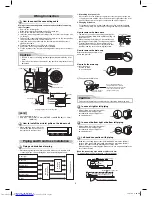
1. After determining the pipe hole position on the mounting plate (

A

), drill 

the pipe hole (

65 mm) at a slight downward slant to the outdoor side.

5

 Mounting screw


4 x 25 

s

CAUTION

Failure to fi rmly install the unit may result in personal injury and property 
damage if the unit falls.

CAUTION

When installing the installation plate with a mounting screw, do not use 
the anchor bolt holes. Otherwise, the unit may fall down and result in 
personal injury and property damage.

Anchor bolt holes

1

 Installation plate

5

 Mounting 

screw

VT

1115551271_(01_EN).indb   3

1115551271_(01_EN).indb   3

12/17/15   3:30 PM

12/17/15   3:30 PM

Summary of Contents for RAS-18BAS Series

Page 1: ...Indoor unit RAS 18 24BKS Outdoor unit RAS 18 24BAS AIR CONDITIONER SPLIT TYPE INSTALLATION MANUAL 1115551271 1115551271_ 01_EN indb C1 12 17 15 3 30 PM Series Series ...

Page 2: ...late 3 Wiring Connection 4 Piping and Drain Hose Installation 4 Indoor Unit Fixing 5 Drainage 5 OUTDOOR UNIT 5 Installation Place 5 Refrigerant Piping Connection 6 Evacuating 6 Wiring Connection 6 Electrical Work 7 OTHERS 7 Gas Leak Test 7 Remote Control A B Selection 7 Test Operation 7 Auto Restart Setting 7 1115551271_ 01_EN indb C2 1115551271_ 01_EN indb C2 12 17 15 3 30 PM 12 17 15 3 30 PM ...

Page 3: ...R DISCONNECTED BEFORE INSTALLATION DO NOT INSTALL NEAR CONCENTRATIONS OF COMBUSTIBLE GAS OR GAS VAPORS FAILURE TO FOLLOW THIS INSTRUCTION CAN RESULT IN FIRE OR EXPLOSION TO PREVENT OVERHEATING THE INDOOR UNIT AND CAUSING A FIRE HAZARD PLACE THE UNIT WELL AWAY MORE THAN 2 M FROM HEAT SOURCES SUCH AS RADIATORS HEATERS FURNACE STOVES ETC WHEN MOVING THE AIR CONDITIONER FOR INSTALLING IT IN ANOTHER PL...

Page 4: ...g wind Use 8 mm or 10 mm anchor bolts and nuts Fixing bolt arrangement of outdoor unit Wall Attach to the front panel Air outlet Drain outlet For the rear left and left piping Insert the cushion between the indoor unit and wall and tilt the indoor unit for better operation Do not allow the drain hose to get slack Make sure to run the drain hose sloped downward Cut the piping hole sloped slightly I...

Page 5: ...y installation of the piping to the outdoor unit A place which allows the front panel to be opened The indoor unit shall be installed as top of the indoor unit comes to at least 2 m height Also it must be avoided to put anything on the top of the indoor unit The center of the pipe hole is above the arrow Pipe hole In case of block brick concrete or similar type walls make 5 mm dia holes in the wal...

Page 6: ... Fix the terminal cover rear plate bushing and air inlet grille on the indoor unit 1 2 3 110 mm 20 mm 10 mm 80 mm Earth line about 15 cm Liquid side Gas side To the forefront of flare Outward form of indoor unit R 30 mm Use polisin polyethylene core or the like for bending pipe Use the handle of screwdriver etc Rear right Rear left Bottom left Left Bottom right Right Die cutting front panel slit C...

Page 7: ...evated position be sure to secure its feet An allowable length of the connecting pipe is up to 15 m An allowable height level is up to 8 m RAS 18BAS and 10 m RAS 24BAS A place where the drain water does not cause any problems Hook here Hook Press unhook Push Push NOTE If the pipe is bent incorrectly the indoor unit may unstably be set on the wall After passing the connecting pipe through the pipe ...

Page 8: ...ts cover and the cord clamp from the outdoor unit 2 Connect the connecting cable to the terminal as identified by the matching numbers on the terminal block of indoor and outdoor unit 3 Insert the power cord and the connecting cable carefully into the terminal block and secure it tightly with screws 4 Use vinyl tape etc to insulate the cords which are not to be used Locate them so that they do not...

Page 9: ... Both are set to A setting in factory shipment The remote control signal is not received when the settings of indoor unit and remote control are different There is no relation between A setting B setting and A room B room when connecting the piping and cables To separate using of remote control for each indoor unit in case of 2 air conditioners are installed near Remote Control B Setup 1 Press RES...

Page 10: ...MEMO 1115551271_ 01_EN indb C3 1115551271_ 01_EN indb C3 12 17 15 3 30 PM 12 17 15 3 30 PM ...

Page 11: ...MEMO 1115551271_ 01_EN indb C4 1115551271_ 01_EN indb C4 12 17 15 3 30 PM 12 17 15 3 30 PM ...

Page 12: ...70 L N 10 60 10 70 10 80 10 1 2 3 L N 1 3 2 A B AWG 16 RESET RESET RESET AWG 12 60245 IEC66 ...

Page 13: ... H30 H14 H17 A H FI ﺗﻨﺒﻴﻪ ﻟـ R410A ﻓﻘﻁ ﻟـ R410A ﻓﻘﻁ ﻟـ R410A ﻓﻘﻁ A R410A RIDGID IMPERIAL ﻗد R410A اﻟﺗﺑرﯾد ﻣﺎدة ﯾﺳﺗﺧدم اﻟذي اﻟﮭواء ﻣﻛﯾف اﻟﺗﺑرﯾد ﻣﺿﺧﺔ ﻓﻲ اﻟﻣوﺟود اﻟزﯾت دﺧول ﺣﺎﻟﺔ ﻓﻲ اﻟﺗﺑرﯾد دورة ﻓﻲ ﻣﺷﻛﻠﺔ ﺗﺣدث ﻣم اﻟوﺣدة ...

Page 14: ... 1 2 اﻟﺗردد ﻋﺎﻟﯾﺔ اﻟﻣوﺟﺎت ﻓﯾﮫ ﺗﺗوﻟد أن ﯾﺣﺗﻣل ﻣﻛﺎن اﻟﻠﺣﺎم وأدوات اﻟﺻوت أﺟﮭزة ﻣن ﺗﺻدر ﻛﺎﻟﺗﻲ اﻟﻣﯾﻛﺎﻧﯾﻛﯾﺔ واﻟﻣﻌدات RAS 18BAS RAS 24BAS ...

Page 15: ... Y F 4 H B C F 590 G H 9 9 B 4 0 N Y F J N 1 6 7 9 F 5 B 6 0 B 0 0 3 3 H 0 7 2 3 0 3 L F G H 1 0 3 0 3 3 9 H 2 1 10 0 0 3 0 3 3 3 9 Y 0 H 0 9 H 0 H0 3 9 H 0 3 9 H 0 0 L F 3 Y J 1 4 8 7 Y 1 N N K 3 4 Q F B K 9 G H 1 F R 2 F 9 H0 3 Y J T 1 H K S 6 H L B 6 7 0 R 4 9 9 K H F D 3 0 5 4 5 2 F8 1 1 F D 3 0 5 4 5 2 F8 ﻣﻢ ٥٢٠ ﻣﻢ ٤٢٠ ﻣﻢ ٤٣ ٨٠ I 9 9 7 0 4 0 H9 5 4 0 N 02 O 3 H N E F8 7 7 F F D z 9 z O P G H ...

Page 16: ...ut line 240mm Offset 23mm from the right side edge is the center of pipe hole To unit out line 120mm 0 23 35 120 180 240 Offset 85mm from the left side edge is the center of pipe hole U T U T YT XT Y UWV VW Ğ ğ Z Y ËĪÎģijÉ ÌĔ Y ÐİĜãÉæěÉ ÏæßĪěÉ þİã ĖÎôğ ġëĩ ĮÎěĪě éÊĠðğ ĖÎôğ ĖÎôğ ÌİėêÓ ÐßĪě U ÒİÎØÔěÉ êİğÊðğ ËĪĔ ÐİûéijÉ ÞĀï īĪÔðğ Ģğ êØėÉ ĩÉ ĝV ĞğZY ËĪÎģijÉ ÌĔ ÌİėêÔěÉ ÐßĪě ĮĔď Ćûĩ Įď ÊĨĔÍÉ ĮÿÊĔïà Ěē ĩ Ğğ...

Page 17: ... ﻣﻢ 108 ﻣﻢ 600 ﻣﻢ 28 ﻢ ﻣ 2 5 ﻣﻢ 90 ﻣﻢ 125 ﻣﻢ 320 ﻣﻢ 86 ﻣﻢ 102 Ø 8 10 A B C ...

Page 18: ... x 0 H 0 K 9 G H 4 7 G 4 H 7 x 4 59 C QL C R 0B 6 7 F I 5 B3 9 2 x 8 3 0 1 Q7 59 9 x 10B 4 F 0 _ B 0 x 9 9 8 R B 9 2 3 F 4 H H B L C 7 F I 5 2 3 0 4 x 0 R H H 4 0 9 C 5 F4 0 z x JB H 4 L L L H 4 4 R H 7 x 5 L L 9 4 93 8 B Q F K 9 9 x z 5 0 10B R 3 4 2 4 2 19 x H 4 B B B J 0 B I 59 x H0 0 I 9 F 10B F 8 59 0 B 9 2 59 H0 B C 19 V G IEC66 60245 8 3 I H07RN F 0 H 4 0 80 B 4 B 59 2 80 9 0 8 3 7 Q7 9 D J...

Page 19: ......

Page 20: ...S e r i e s S e r i e s ...

Reviews: